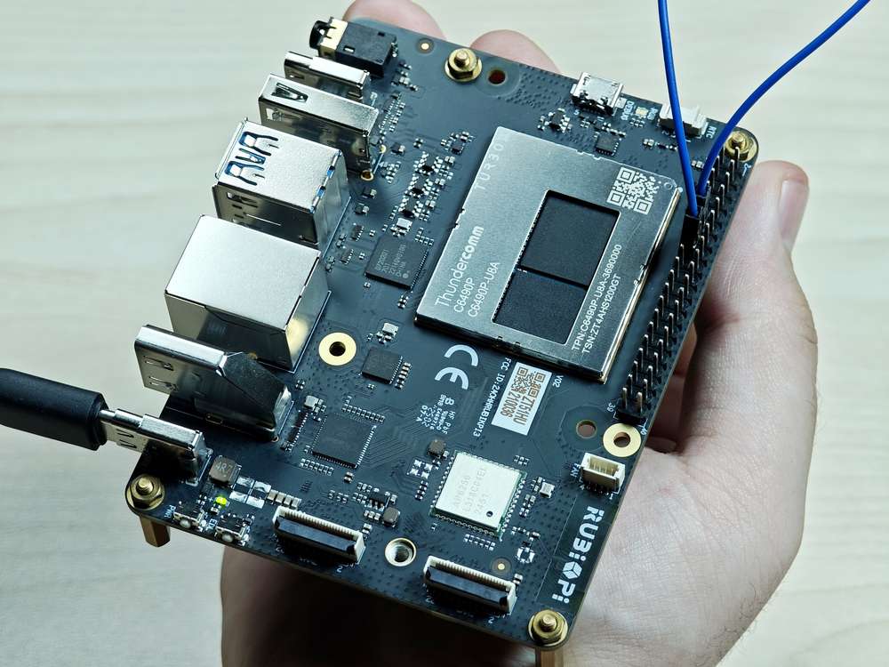
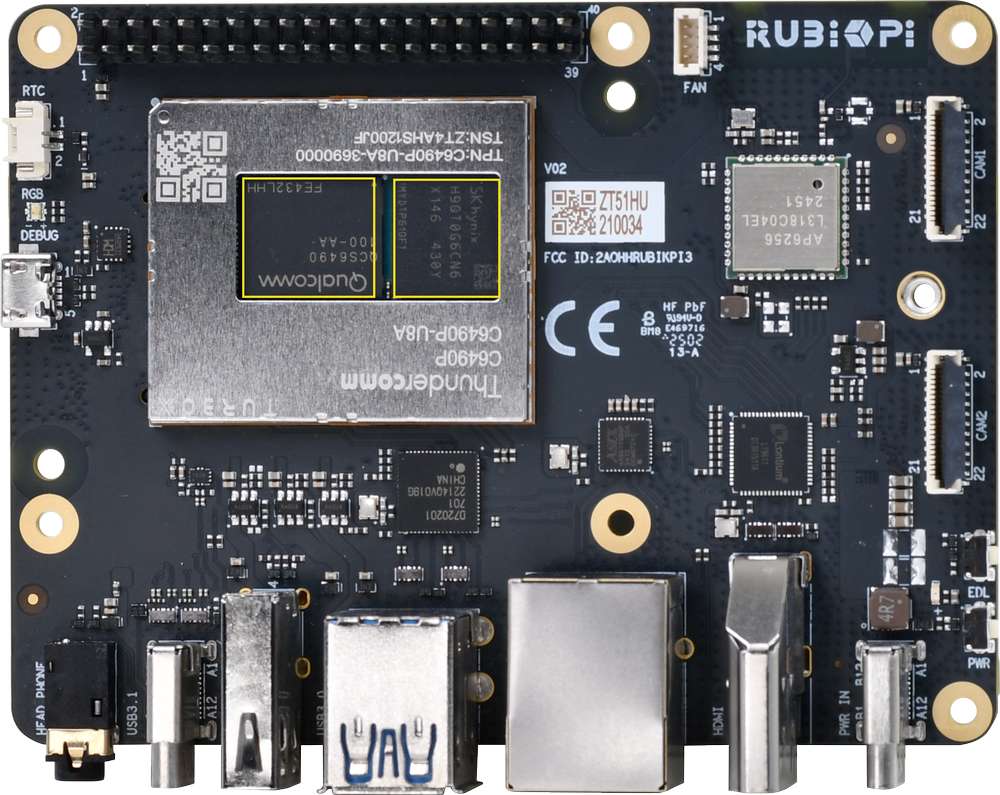
外设与接口
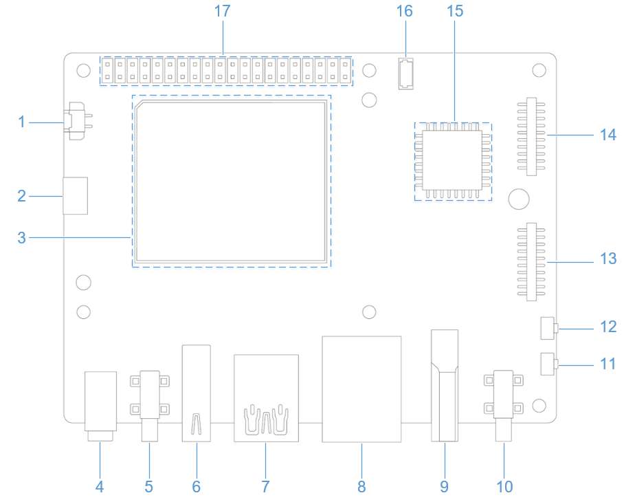
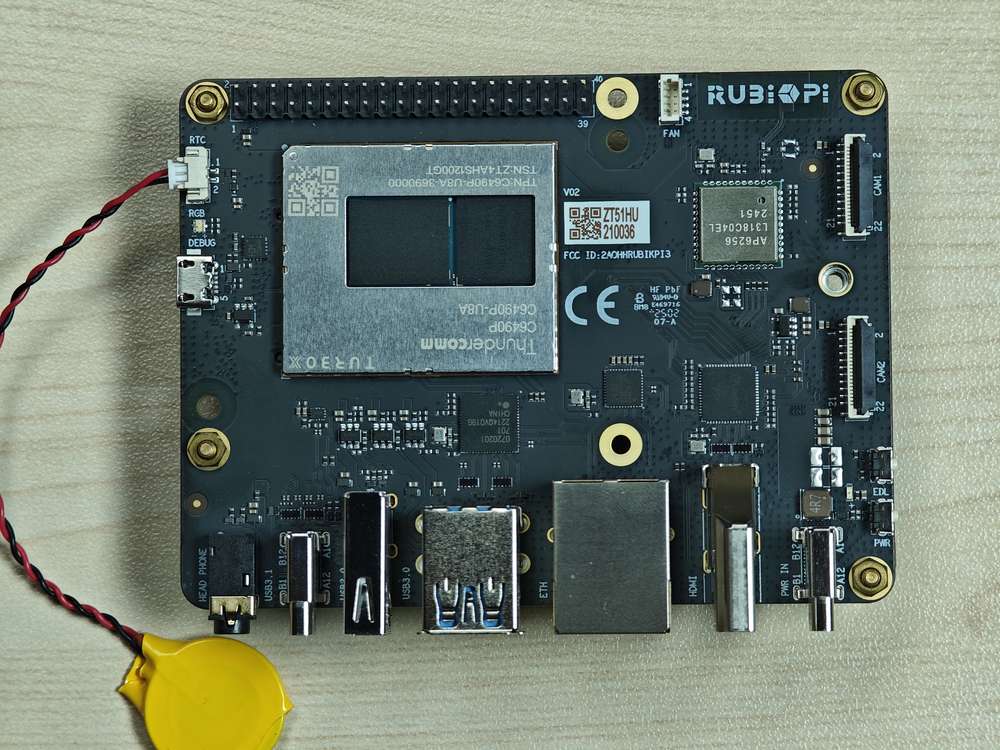
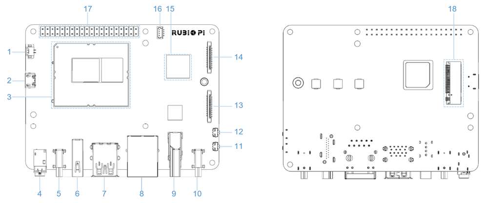
硬件资源图
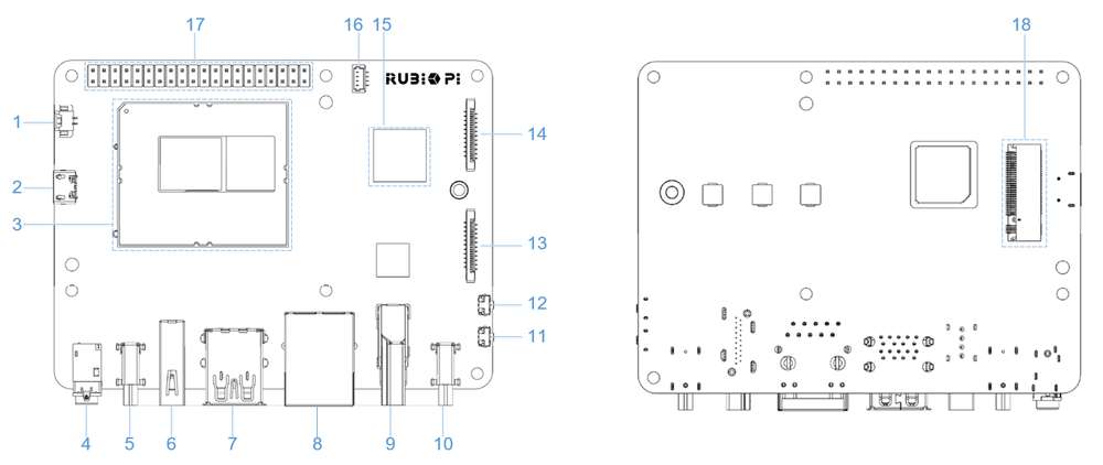
| 序号 | 接口 | 序号 | 接口 |
|---|---|---|---|
| 1 | RTC 电池接口 | 10 | Type-C 电源接口 |
| 2 | Micro USB (UART 调试) | 11 | PWR 按键 |
| 3 | TurboX C6490P SOM | 12 | EDL 按键 |
| 4 | 3.5mm 耳机接口 | 13 | 摄像头接口 2 |
| 5 | USB Type-C with DP (USB 3.1) | 14 | 摄像头接口 1 |
| 6 | USB Type-A (USB 2.0) | 15 | Wi-Fi/蓝牙模块 |
| 7 | 2 x USB Type-A (USB 3.0) | 16 | 风扇接口 |
| 8 | 1000M 以太网 | 17 | 40-pin 连接器 |
| 9 | HDMI OUT | 18 | M.2 Key M 接口 |
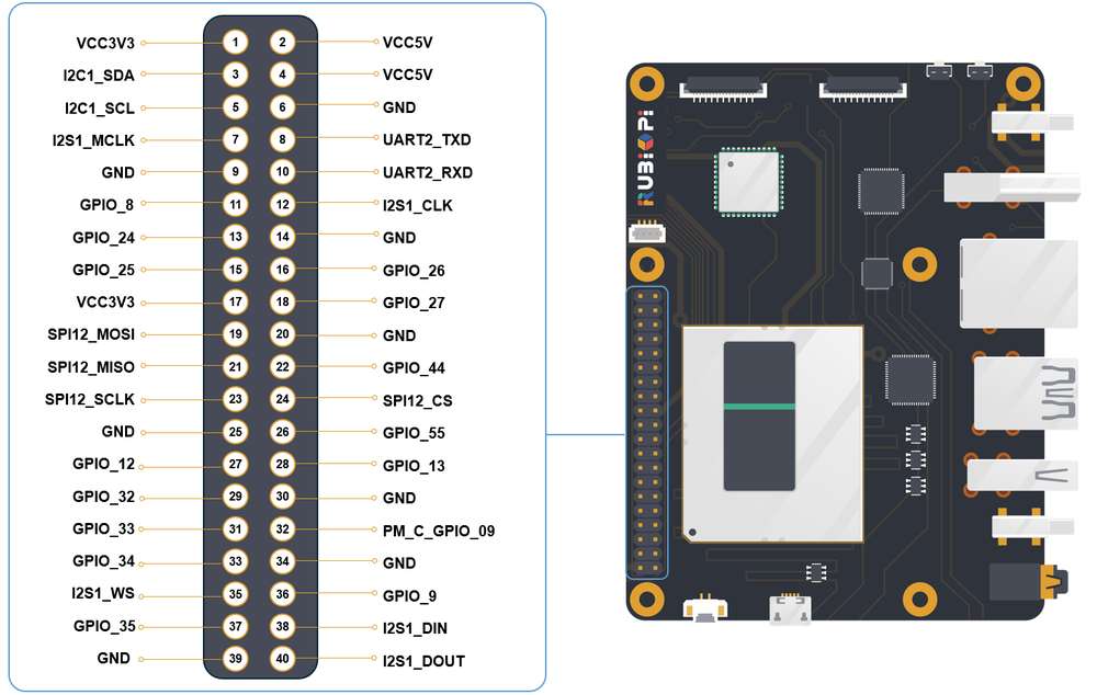
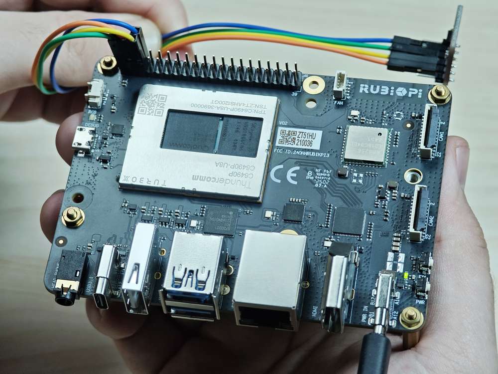
40 pin 连接器
GPIO
魔方派 3 适配了 WiringRP(基于高性能 GPIO 编程库 WiringPi),推荐使用 WiringRP 来控制 GPIO,和对 GPIO 编程。关于 WiringRP 详细信息可访问 https://github.com/rubikpi-ai/WiringRP 查看。
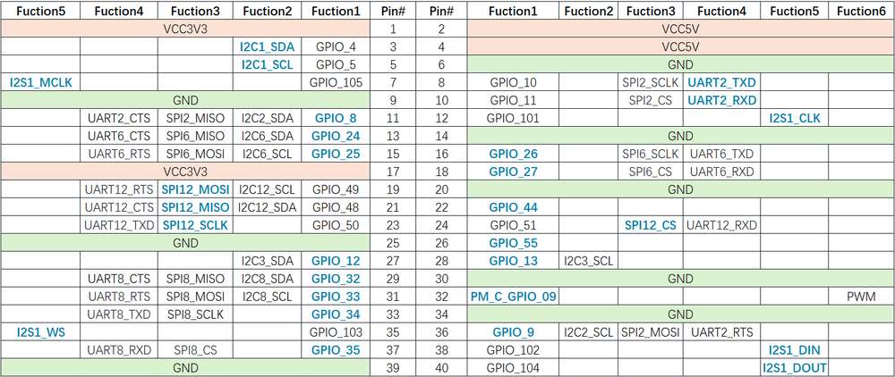
引脚分布
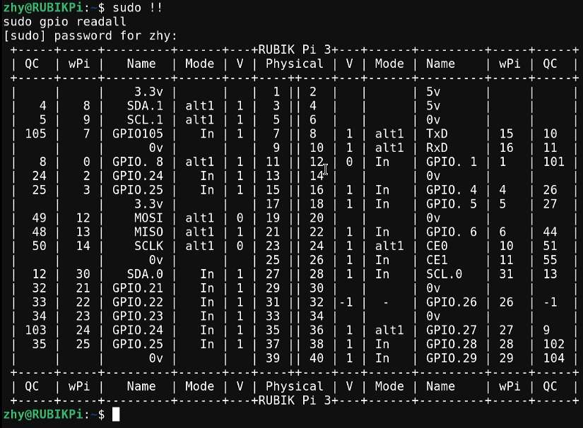
下图是 魔方派 3 40-pin 连接器的引脚默认功能,其中大部分引脚和树梅派 40-pin 连接器引脚的默认功能兼容。

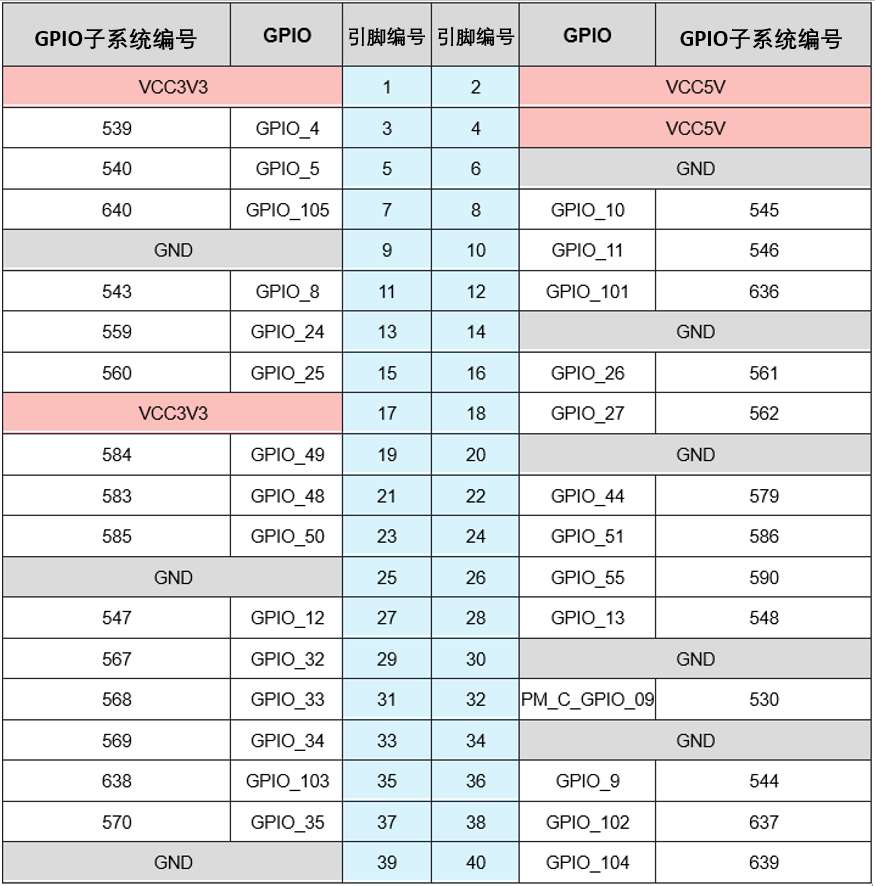
下表是 40-pin连接器支持的所有功能,图中蓝色字体表明默认功能。

使用 shell 命令控制
在魔方派 3 中执行下面的步骤控制 GPIO。
下面命令需要使用 root 权限:
执行
su root命令,换到 root 用户
- 帐号: root
- 密码: root
或在普通用户下,在命令前加入
sudo,如sudo gpio readall,根据提示输入用户的登录密码。
-
使用 WiringRP 相关命令
-
查看 GPIO 状态
gpio readall
-
设置 GPIO 模式
gpio mode 15 in             # 将15号引脚模式置为输入
gpio pins                   # 查看更改之后的状态
gpio mode 15 out            # 将15号引脚模式置为输出
gpio pins # 查看更改之后的状态 -
设置引脚电平
gpio write 15 1             # 将15号引脚置为高电平
gpio read 15                # 读取更改后引脚状态
gpio write 15 0             # 将15号引脚置为低电平
gpio read 15                # 读取更改后引脚状态
-
-
操作 /sys/class/gpio 下相关节点
GPIO 子系统的编号如下表。
- 进入 /sys/class/gpio 目录:
cd /sys/class/gpio
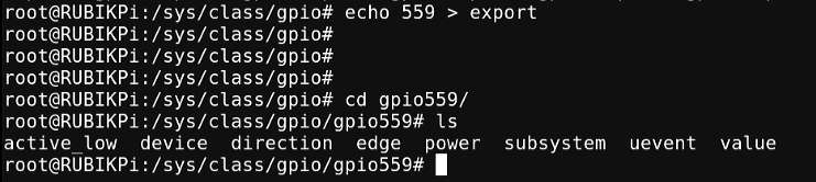
- 将要控制的 GPIO 导出,如控制 13 号引脚 GPIO_24:
echo 559 > export
- 进入到 gpio559 目录设置 GPIO 属性:
cd gpio559
ls
-
direction(方向):
- 输入:in
- 输出:out
-
value(值):
- 低电平:0
- 高电平:1
-
edge (中断边沿):
- 上升沿触发:rising
- 下�降沿触发:falling
- 双边沿触发:both
- 禁用中断:none
如设置 13 号引脚输出高电平:
echo out > direction
echo 1 > value
取消导出 13 号引脚到用户空间:
echo 559 > unexport
使用 WiringRP (C) 控制
WiringRP 库中提供了一系列的 API 函数,用更少的逻辑实现控制。
- 以下代码示例,代码将 13 号引脚设置为输出, 15 号引脚设置为输入,循环检测 15 号引脚的电平状态:
#include <stdio.h>
#include <wiringPi.h>

int main (void)
{
  wiringPiSetup () ;
  pinMode (13, OUTPUT) ;
  pinMode (15, INPUT) ;

  for (;;)
  {
    digitalWrite (13, HIGH) ;        // On
    printf("%d\n", digitalRead (15));        // On
    delay (1000) ;                // mS
    digitalWrite (13, LOW) ;        // Off
    printf("%d\n", digitalRead (15));        // On
    delay (1900) ;
  }

  return 0 ;
}
-
编译程序
- 在魔方派 3 中编译
adb push gpio.c /opt
adb shell
su
cd /opt
gcc gpio.c -o gpio -lwiringPi备注若无 gcc 命令,可执行
apt install gcc命令进行安装。 -
将 13 和 15 号引脚使用杜邦线短接,测试 GPIO 电平控制和电平读取情况,如下图所示:
注意注意引脚顺序,请勿将电源和地引脚短接,否则可能会造成板子损坏。

运行如下命令:
cd /opt
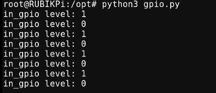
./gpio程序运行结果如下:

使用 WiringRP-Python 控制
WiringRP 库中提供了一系列的 API 函数,用更少的逻辑实现控制。
-
下方截取代码是使用 WiringRP 库操作 GPIO 的示例,其中将 13 号引脚设置为输出,15 号引脚设置为输入,循环检测 15 号引脚的电平状态。
import wiringpi
import time

wiringpi.wiringPiSetup()
wiringpi.pinMode(13, 1)
wiringpi.pinMode(15, 0)
wiringpi.digitalRead(15)

while True:
    wiringpi.digitalWrite(13,1)
    pin_level = wiringpi.digitalRead(15)
    print(f"in_gpio level: {pin_level}")

    time.sleep(1)

    wiringpi.digitalWrite(13,0)
    pin_level = wiringpi.digitalRead(15)
    print(f"in_gpio level: {pin_level}")

time.sleep(1) -
将 gpio.py 传输到 魔方派 3 中,如使用 ADB 传输。
adb push gpio.py /opt -
将 13 和 15 号引脚使用杜邦线短接,测试 GPIO 电平控制和电平读取情况,如下图所示
注意注意引脚顺序,请勿将电源和地引脚短接,否则可能会造成板子损坏。

�运行如下命令:
cd /opt
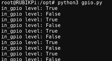
python3 gpio.py程序运行结果如下:
使用 Python 程序控制
-
可使用 Python 的 periphery 库控制 GPIO,可在魔方派 3 中使用下面命令进行安装:
apt install python3-periphery -
下方截取代码是使用 periphery 库操作 GPIO 的示例,其中将 13 号引脚设置为输出,15 号引脚设置为输入,循环检测 15 号引脚的电平状态。
from periphery import GPIO
import time

out_gpio = GPIO(559, "out")
in_gpio = GPIO(560, "in")

try:
    while True:
        try:
            out_gpio.write(True)
            pin_level = in_gpio.read()
            print(f"in_gpio level: {pin_level}")

            out_gpio.write(False)
            pin_level = in_gpio.read()
            print(f"in_gpio level: {pin_level}")

            time.sleep(1)

        except KeyboardInterrupt:
            out_gpio.write(False)
            break

except IOError:
    print("Error")

finally:
    out_gpio.close()
in_gpio.close() -
将 gpio.py 传输到 魔方派 3 中,如使用 ADB 传输。
adb push gpio.py /opt -
将 13 和 15 号引脚使用杜邦线短接测试 GPIO 电平控制和电平读取情况,如下图所示:
注意注意引脚顺序,请勿将电源和地引脚短接,否则可能会造成板子损坏。

运行如下命令:
cd /opt
python3 gpio.py
程序运行结果如下:
使用 C 语言程序控制
-
以下代码示例,代码将 13 号引脚设置为输出, 15 号引脚设置为输入,循环检测 15 号引脚的电平状态:
#include <stdio.h>
#include <stdlib.h>
#include <unistd.h>

int out_gpio = 559;
int in_gpio = 560;

int main() {
    char export_path[50] = {};
    char export_command[100] = {};
    snprintf(export_path, sizeof(export_path), "/sys/class/gpio/export");
    snprintf(export_command, sizeof(export_command), "echo %d > %s ", out_gpio, export_path);
    system(export_command);
    snprintf(export_command, sizeof(export_command), "echo %d > %s ", in_gpio, export_path);
    system(export_command);

    char direction_path[50] = {};
    snprintf(direction_path, sizeof(direction_path), "/sys/class/gpio/gpio%d/direction", out_gpio);
    FILE *direction_file = fopen(direction_path, "w");
    if (direction_file == NULL) {
        perror("Failed to open GPIO direction file");
        return -1;
    }
    fprintf(direction_file, "out");
    fclose(direction_file);

    snprintf(direction_path, sizeof(direction_path), "/sys/class/gpio/gpio%d/direction", in_gpio);
    direction_file = fopen(direction_path, "w");
    if (direction_file == NULL) {
        perror("Failed to open GPIO direction file");
        return -1;
    }
    fprintf(direction_file, "in");
    fclose(direction_file);

    char value_in_path[50] = {};
    char value_out_path[50] = {};
    char cat_command[100] = {};
    snprintf(value_out_path, sizeof(value_out_path), "/sys/class/gpio/gpio%d/value", out_gpio);
    snprintf(value_in_path, sizeof(value_in_path), "/sys/class/gpio/gpio%d/value", in_gpio);
    snprintf(cat_command, sizeof(cat_command), "cat %s", value_in_path);

    FILE *value_out_file = fopen(value_out_path, "w");
    if (value_out_file == NULL) {
        perror("Failed to open GPIO value file");
        return -1;
    }

    for (int i = 0; i < 5; i++) {
        fprintf(value_out_file, "1");
        fflush(value_out_file);

        system(cat_command);
        sleep(1);

        fprintf(value_out_file, "0");
        fflush(value_out_file);

        system(cat_command);
        sleep(1);
    }

    fclose(value_out_file);

    char unexport_path[50] = {};
    char unexport_command[100] = {};
    snprintf(unexport_path, sizeof(unexport_path), "/sys/class/gpio/unexport");
    snprintf(unexport_command, sizeof(unexport_command), "echo %d > %s ", out_gpio, unexport_path);
    system(unexport_command);
    snprintf(unexport_command, sizeof(unexport_command), "echo %d > %s ", in_gpio, unexport_path);
    system(unexport_command);

    return 0;
} -
编译程序:
-
交叉编译。
aarch64-qcom-linux-gcc gpio.c -o gpio --sysroot=/home/zhy/qcom_sdk_meta/sysroots/armv8-2a-qcom-linux/ -
在魔方派 3 中编译:
adb push gpio.c /opt
adb shell
su
cd /opt
gcc gpio.c -o gpio备注若无 gcc 命令,可执行
apt install gcc命令进行安装。若使用了交叉编译,需将 gpio 传输到 魔方派 3 中,如使用 ADB 传输:
adb push gpio /opt
-
-
将 13 和 15 号引脚使用杜邦线短接,测试 GPIO 电平控制和电平读取情况,如下图所示:
注意注意引脚顺序,请勿将电源和地引脚短接,否则可能会造成板子损坏。
运行如下命令:
cd /opt
./gpio
程序运行结果如下:

I2C
I2C 是飞利浦公司在 20 世纪 80 年代开发的一种双向 2 线制总线,用于实现高效的 IC 间控制总线。总线上的每个设备都有其唯一的地址(由飞利浦公司领导的 I2C 总机构注册)。I2C 核心支持多控制器模式,以及 10 位目标地址和 10 位可扩展地址。关于 I2C 的更多信息,请参阅 https://www.i2c-bus.org/fileadmin/ftp/i2c_bus_specification_1995.pdf
魔方派 3 适配了 WiringRP(基于高性能 GPIO 编程库 WiringPi ) ,推荐使用 WiringRP 来控制 I2C,和对 I2C 编程。关于 WiringRP 详细信息可访问 https://github.com/rubikpi-ai/WiringRP 查看。
引脚分布
下图是 魔方派 3 40-pin 连接器的引脚默认功能,其中大部分引脚和树梅派 40-pin 连接器引脚的默认功能兼容。
3 号引脚和 5 号引脚默认已设置配为 I2C1。
下表是 40-pin 连接器支持的所有功能,图中蓝色字体表明默认功能。

使用 shell 命令测试
在魔方派 3 中执行下面步骤控制 I2C 总线。
-
使用 WiringRP 相关命令:
./gpio -x ads1115:100:10 aread 100 #通过 I2C 总线读取 ADS1115 设备的模拟信号值 -
使用 i2cdetect 工具
-
查看 I2C1 接口上的设备:
i2cdetect -a -y -r 1 -
读取地址为 0x38 设备的全部寄存器:
i2cdump -f -y 1 0x38 -
向地址为 0x38 设备的 0x01 寄存器地址写入 0xaa:
i2cset -f -y 1 0x38 0x01 0xaa -
读取地址为 0x38 的设备,寄存器地址为0x01处的数值:
i2cget -f -y 1 0x38 0x01
-
若无 i2cdetect 等命令,可执行 apt install i2c-tools 命令进行安装。
使用 WiringRP (C) I2C 通信
WiringRP 库中提供了一系列的 API函数,用更少的逻辑实现控制。
-
以下代码示例,I2C1总线和地址为0x38的设备进行通信,向设备0x01地址处写入0xaa:
#include <wiringPi.h>
#include <wiringPiI2C.h>
#include <stdio.h>
#include <stdlib.h>
#include <unistd.h>

#define I2C_ADDRESS 0x38

int main(void)
{
    int fd;

    if (wiringPiSetup() == -1) {
        exit(1);
    }

    fd = wiringPiI2CSetup(1, I2C_ADDRESS);
    if (fd == -1) {
        exit(1);
    }

    unsigned char data[2];
    if (read(fd, data, 2) != 2) {
        exit(1);
    }

    wiringPiI2CWriteReg8(fd, 0x01, 0xaa) ;

    close(fd);
    return 0;
} -
编译程序
-
在魔方派 3 中编译
adb push gpio.c /opt
adb shell
su
cd /opt
gcc i2c.c -o i2c -lwiringPi备注若无 gcc 命令,可执行
apt install gcc命令进行安装。
-
-
将 3 和 5 号引脚连接 I2C 传感器,验证 I2C 总线通信,如下图所示
注意注意引脚顺序,请勿将电源和地引脚短接,否则可能会造成板子损坏。
运行如下命令运行程序:
cd /opt
./i2c
使用 WiringRP-Python I2C 通信
WiringRP 库中提供了一系列的 API 函数,用更少的逻辑实现控制。
-
以下代码示例,使用 I2C1 总线和地址为 0x38 的设备进行通信,向设备 0x01 地址处写入 0xaa:
import wiringpi as wpi

wpi.wiringPiSetup()
fd=wpi.wiringPiI2CSetup(0x38, 1)
wpi.wiringPiI2CWriteReg8 (fd, 0x01, 0xaa) -
将 i2c.py 传输到 魔方派 3 中,如使用 ADB 传输。
adb push i2c.py /opt -
将 3 和 5 号引脚连接 I2C 传感器,验证 I2C 总线通信,如下图所示:
注意注意引脚顺序,请勿将电源和地引脚短接,否则可能会造成板子损坏。

运行如下命令:
cd /opt
python3 i2c.py
使用 Python 程序 I2C 通信
-
可使用 Python 的 smbus 库控制 I2C,可在魔方派 3 中使用下面命令进行安装:
apt install python3-smbus -
以下代码示例,使用 I2C1 总线和地址为 0x38 的设备进行通信,向设备 0x01 地址处写入 0xaa:
import smbus

def main():
    data = [0x01, 0xaa]

    try:
        i2c_bus = smbus.SMBus(1)

        print("i2cdetect addr : ", end="")
        for address in range(0x7F):
            try:
                i2c_bus.write_i2c_block_data(address, 0, data)
                print("0x{:02X},".format(address), end="")
            except OSError:
                pass

        print()

    except Exception as e:
        print(f"An error occurred: {e}")

    finally:
        if i2c_bus:
            i2c_bus.close()

if __name__ == "__main__":
main() -
将 i2c.py 传输到 魔方派 3中,如果使用 ADB 传输,命令如下:
adb push i2c.py /opt -
将 3 和 5 号引脚连接 I2C 传感器,验证 I2C 总线通信,如下图所示:
注意注意引脚顺序,请勿将电源和地引脚短接,否则可能会造成板子损坏。

运行如下命令:
cd /opt
python3 i2c.py
程序运行结果如下:

使用 C 语言程序 I2C 通信
-
以下代码示例,I2C1 总线和地址为 0x38 的设备进行通信,向设备 0x01 地址处写入 0xaa:
#include <stdio.h>
#include <stdlib.h>
#include <stdint.h>
#include <fcntl.h>
#include <unistd.h>
#include <linux/i2c-dev.h>
#include <sys/ioctl.h>

#define I2C_DEVICE_PATH "/dev/i2c-1"

int main() {
    uint8_t data[2] = {0x01,0xaa};

    const char *i2c_device = I2C_DEVICE_PATH;
    int i2c_file;

    if ((i2c_file = open(i2c_device, O_RDWR)) < 0) {
        perror("Failed to open I2C device");
        return -1;
    }

    ioctl(i2c_file, I2C_TENBIT, 0);
    ioctl(i2c_file, I2C_RETRIES, 5);

    printf("i2cdetect addr : ");
    for (int x = 0; x < 0x7f; x++)
    {
        if (ioctl(i2c_file, I2C_SLAVE, x) < 0) {
            perror("Failed to set I2C slave address");
            close(i2c_file);
            return -1;
        }

        if (write(i2c_file, data, 2) == 2)
        {
            printf("0x%x,", x);
        }
    }

    close(i2c_file);
    printf("\r\n");

    return 0;
} -
编译程序:
-
交叉编译。
aarch64-qcom-linux-gcc i2c.c -o i2c --sysroot=/home/zhy/qcom_sdk_meta/sysroots/armv8-2a-qcom-linux/ -
在魔方派 3 中编译
adb push i2c.c /opt
adb shell
su
cd /opt
gcc i2c.c -o i2c备注若无 gcc 命令,可执行
apt install gcc命令进行安装。若使用的交叉编译,需要将 i2c 传输到 魔方派 3 中,如果使用 ADB 传输,命令如下:
adb push i2c /opt
-
-
将 3 和 5 号引脚连接 I2C 传感器,验证 I2C 总线通信,如下图所示:
注意注意引脚顺序,请勿将电源和地引脚短接,否则可能会造成板子损坏。

运行如下命令:
cd /opt
./i2c
程序运行结果如下:

SPI
串行外设接口 (SPI) 是在全双工模式下工作的同步串行数据链路。SPI 又称为 4 线制串行总线。
魔方派 3 适配了 WiringRP(基于高性能 GPIO 编程库 WiringPi),推荐使用 WiringRP 来控制 SPI,和对 SPI 编程。关于 WiringRP 详细信息可访问 https://github.com/rubikpi-ai/WiringRP 查看。
引脚分布
下图是 魔方派 3 40-pin 连接器的引脚默认功能,其中大部分引脚和树梅派 40-pin 连接器引脚的默认功能兼容。

19 号、21 号、23 �号、24 号引脚默认已设置配为 SPI。
下表是 40-pin 连接器支持的所有功能,图中蓝色字体表明默认功能。
使用 WiringRP (C) SPI 通信
WiringRP 库中提供了一系列的 API 函数,用更少的逻辑实现控制。
-
以下代码示例,代码使用 SPI 总线进行数据收发通信:
#include <wiringPi.h>
#include <wiringPiSPI.h>
#include <stdio.h>
#include <stdlib.h>

int main(void)
{
    int fd;
    unsigned char send_data[64] =  "hello world!";
    unsigned char read_data[64];

    if(wiringPiSetup() == -1)
        exit(1);

    fd = wiringPiSPISetup(0, 1000000);
    if(fd < 0)
        exit(2);

        printf("\rtx_buffer: \n %s\n ", send_data);
    // Send and receive data
    if(wiringPiSPIDataRW(0, send_data, sizeof(send_data)) < 0)
        exit(3);
        printf("\rtx_buffer: \n %s\n ", send_data);


    return 0;
} -
编译程序
-
在魔方派 3 中编译
adb push spi.c /opt
adb shell
su
cd /opt
gcc spi.c -o spi -lwiringPi备注若无 gcc 命令,可执行
apt install gcc命令进行安装。
-
-
将 19 号引脚和 21 号引脚使用杜邦线短接,验证 SPI 总线通信,如下图所示:
注意注意引脚顺序,请勿将电源和地引脚短接,否则可能会造成板子损坏。
运行如下命令:
cd /opt
./spi
程序执行结果如下:

使用 WiringRP-Python SPI通信
WiringRP 库中提供了一系列的 API 函数,用更少的逻辑实现控制。
-
以下代码示例,代码使用 SPI 总线进行数据收发通信:
import wiringpi as wpi

wpi.wiringPiSetup()

wpi.wiringPiSPISetup(0, 8000000)

tx_buffer = bytes([72, 101, 108, 108, 111])
print("tx_buffer:\n\r ", tx_buffer)
retlen, rx_buffer = wpi.wiringPiSPIDataRW(0, tx_buffer)
print("rx_buffer:\n\r ", rx_buffer)
-
将 spi.py 传输到 魔方派 3 中,如使用 ADB 传输。
adb push spi.py /opt -
将 19 号引脚和 21 号引脚使用杜邦线短接,验证 SPI 总线通信,如下图所示:
注意注意引脚顺序,请勿将电源和地引脚短接,否则可能会造成板子损坏。

运行如下命令:
python3 spi.py程序执行结果如下:

使用 Python 程序 SPI 通信
-
可使用 Python 的 spidev 库进行 SPI 通信,spidev 库可在魔方派 3 中使用下面命令进行安装:
apt install python3-spidev -
以下代码示例,代码使用 SPI 总线进行数据收发通信:
import spidev

def main():
    tx_buffer = [ord(char) for char in "hello world!"]
    rx_buffer = [0] * len(tx_buffer)

    try:
        spi = spidev.SpiDev()
        spi.open(12, 0)
        spi.max_speed_hz = 1000000

        rx_buffer = spi.xfer2(tx_buffer[:])
        print("tx_buffer:\n\r", ''.join(map(chr, tx_buffer)))
        print("rx_buffer:\n\r", ''.join(map(chr, rx_buffer)))

    except Exception as e:
        print(f"An error occurred: {e}")

    finally:
        if spi:
            spi.close()

if __name__ == "__main__":
main() -
将 spi.py 传输到 魔方派 3 中,如果使用 ADB 传输,命令如下:
adb push spi.py /opt -
将 19 号引脚和 21 号引脚使用杜邦线短接,验证 SPI 总线通信,如下图所示:
注意注意引脚顺序,请勿将电源和地引脚短接,否则可能会造成板子损坏。

运行如下命令:
python3 spi.py程序执行结果如下:
使用 C 语言程序 SPI 通信
-
以下代码示例,代码使用 SPI 总线进行数据收发通信:
#include <stdio.h>
#include <stdlib.h>
#include <stdint.h>
#include <fcntl.h>
#include <unistd.h>
#include <linux/spi/spidev.h>
#include <sys/ioctl.h>

#define SPI_DEVICE_PATH "/dev/spidev12.0"

int main() {
    int spi_file;
    uint8_t tx_buffer[50] = "hello world!";
    uint8_t rx_buffer[50];

    // Open the SPI device
    if ((spi_file = open(SPI_DEVICE_PATH, O_RDWR)) < 0) {
        perror("Failed to open SPI device");
        return -1;
    }

    // Configure SPI mode and bits per word
    uint8_t mode = SPI_MODE_0;
    uint8_t bits = 8;
    if (ioctl(spi_file, SPI_IOC_WR_MODE, &mode) < 0) {
        perror("Failed to set SPI mode");
        close(spi_file);
        return -1;
    }
    if (ioctl(spi_file, SPI_IOC_WR_BITS_PER_WORD, &bits) < 0) {
        perror("Failed to set SPI bits per word");
        close(spi_file);
        return -1;
    }

    // Perform SPI transfer
    struct spi_ioc_transfer transfer = {
        .tx_buf = (unsigned long)tx_buffer,
        .rx_buf = (unsigned long)rx_buffer,
        .len = sizeof(tx_buffer),
        .delay_usecs = 0,
        .speed_hz = 1000000,  // SPI speed in Hz
        .bits_per_word = 8,
    };

    if (ioctl(spi_file, SPI_IOC_MESSAGE(1), &transfer) < 0) {
        perror("Failed to perform SPI transfer");
        close(spi_file);
        return -1;
    }

     /* Print tx_buffer and rx_buffer*/
    printf("\rtx_buffer: \n %s\n ", tx_buffer);
    printf("\rrx_buffer: \n %s\n ", rx_buffer);

    // Close the SPI device
    close(spi_file);

    return 0;
} -
编译程序:
-
交叉编译。
aarch64-qcom-linux-gcc spi.c -o spi --sysroot=/home/zhy/qcom_sdk_meta/sysroots/armv8-2a-qcom-linux/ -
在魔方派 3 中编译
adb push spi.c /opt
adb shell
SU
cd /opt
gcc spi.c -o spi备注若无 gcc 命令,可执行
apt install gcc命令进行安装。 -
若使用的交叉编译,需要将 spi 传输到 魔方派 3 中,如果使用 ADB 传输,命令如下:
adb push spi /opt
-
-
将 19 号引脚和 21 号引脚使用杜邦线短接,验证 SPI 总线通信,如下图所示:
注意注意引脚顺序,请勿将电源和地引脚短接,否则可能会造成板子损坏。

运行如下命令:
cd /opt
./spi
程序执行结果如下:
UART
魔方派 3 适配了 WiringRP(基于高性能 GPIO 编程库 WiringPi),推荐使用 WiringRP 来控制 UART,和对 UART 编程。关于 WiringRP 详细信息可访问 https://github.com/rubikpi-ai/WiringRP 查看。
引脚分布
下图是 魔方派 3 40-pin 连接器的引脚默认功能,其中大部分引脚和树梅派 40-pin 连接器引脚的默认功能兼容。

8 号和 10 号引脚默认已设置配为 UART,设备节点为 /dev/ttyHS2。
下表是 40-pin 连接器支持的所有功能,图中蓝色字体表明默认功能。

使用 shell 命令测试
在魔方派 3 中 使用下面命令控制串口通信
-
使用 stty 工具配置串口,如下将串口的输入速率和输出速率都设置为 115200,并关闭回显:
stty -F /dev/ttyHS2 ispeed 115200 ospeed 115200
stty -F /dev/ttyHS2 -echo -
在魔方派 3 上开启两个终端,将 8 号引脚和 10 号引脚使用杜邦线短接,分别执行下面命令,接收端会回显发送端的内容:
注意注意引脚顺序,请勿将电源和地引脚短接,否则可能会造成板子损坏。
echo "hello world!" > /dev/ttyHS2  # 发送端
cat /dev/ttyHS2 # 接收端
使用 WiringRP (C) UART通信
WiringRP 库中提供了一系列的 API 函数,用更少的逻辑实现控制。
-
以下代码示例,使用UART进行数据收发通信:
#include <stdio.h>
#include <string.h>
#include <errno.h>

#include <wiringPi.h>
#include <wiringSerial.h>

int main ()
{
  int fd ;
  int count ;
  unsigned int nextTime ;

  if ((fd = serialOpen ("/dev/ttyHS2", 115200)) < 0)
  {
    fprintf (stderr, "Unable to open serial device: %s\n", strerror (errno)) ;
    return 1 ;
  }

  if (wiringPiSetup () == -1)
  {
    fprintf (stdout, "Unable to start wiringPi: %s\n", strerror (errno)) ;
    return 1 ;
  }


  char tx_buffer[] = "hello world!\n";
  for (count = 0 ; count < sizeof(tx_buffer) ; count++)
  {
    serialPutchar (fd, tx_buffer[count]) ;
    delay (3) ;
    printf ("%c", serialGetchar (fd)) ;
  }
  printf ("\n") ;

  return 0 ;
} -
编译程序:
-
在魔方派 3 中编译
adb push uart.c /opt
adb shell
su
cd /opt
gcc uart.c -o uart -lwiringPi备注若无 gcc 命令,可执行
apt install gcc命令进行安装。
-
-
将 8 号引脚和 10 号引脚使用杜邦线短接,验证串口通信,如下图所示:
注意注意引脚顺序,请勿将电源和地引脚短接,否则可能会造成板子损坏。

运行如下命令:
cd /opt
./uart
程序执行结果如下:

使用 WiringRP-Python UART 通信
WiringRP 库中提供了一系列的 API 函数,用更少的逻辑实现控制。
-
以下代码示例,使用 UART 进行数据收发通信:
import wiringpi

serial = wiringpi.serialOpen('/dev/ttyHS2', 115200)

wiringpi.serialPuts(serial, "hello world")

received_data = []
c = wiringpi.serialGetchar(serial);
received_data.append(chr(c))

cnt = wiringpi.serialDataAvail(serial);
for i in range(cnt):
    c = wiringpi.serialGetchar(serial);
    received_data.append(chr(c))

print("Received:", received_data)

wiringpi.serialClose(serial) -
将 uart.py 传输到 魔方派 3 中,如果使用 ADB 传输,命令如下:
adb push uart.py /opt -
将 8 号引脚和 10 号引脚使用杜邦线短接,验证串口通信,如下图所示:
注意注意引脚顺序,请勿将电源和地引脚短接,否则可能会造成板子损坏。
运行如下命令:
cd /opt
python3 uart.py
程序执行结果如下:

使用 Python 程序 UART 通信
-
可使用 Python 的 serial 库进行 UART 通信,可在魔方派 3 中使用下面命令进行安装:
apt install python3-serial -
以下代码示例,使用 UART 进行数据收发通信:
import serial
import time

with serial.Serial(
    "/dev/ttyHS2",
    baudrate=115200,
    bytesize=serial.EIGHTBITS,
    stopbits=serial.STOPBITS_ONE,
    parity=serial.PARITY_NONE,
    timeout=1,

) as uart3:
    uart3.write(b"Hello World!\n")
    buf = uart3.read(128)
    print("Raw data:\n", buf)
    data_strings = buf.decode("utf-8")
print("Read {:d} bytes, printed as string:\n {:s}".format(len(buf), data_strings)) -
将 uart.py 传输到 魔方派 3 中,如果使用 ADB 传输,命令如下:
adb push uart.py /opt -
将 8 号引脚和 10 号引脚使用杜邦线短接,验证串口通信,如下图所示:
注意注意引脚顺序,请勿将电源和地引脚短接,否则可能会造成板子损坏。

运行如下命令:
python3 uart.py
程序执行结果如下:

使用 C 语言程序 UART 通信
-
以下代码示例,使用 UART 进行数据收发通信:
#include <stdio.h>
#include <stdlib.h>
#include <string.h>
#include <fcntl.h>
#include <termios.h>
#include <unistd.h>

int main() {
    int serial_port_num = 2;
    char serial_port[15];

    sprintf(serial_port,"/dev/ttyHS%d",serial_port_num);
    int serial_fd;

    serial_fd = open(serial_port, O_RDWR | O_NOCTTY);
    if (serial_fd == -1) {
        perror("Failed to open serial port");
        return 1;
    }

    struct termios tty;
    memset(&tty, 0, sizeof(tty));

    if (tcgetattr(serial_fd, &tty) != 0) {
        perror("Error from tcgetattr");
        return 1;
    }

    cfsetospeed(&tty, B9600);
    cfsetispeed(&tty, B9600);

    tty.c_cflag &= ~PARENB;
    tty.c_cflag &= ~CSTOPB;
    tty.c_cflag &= ~CSIZE;
    tty.c_cflag |= CS8;

    if (tcsetattr(serial_fd, TCSANOW, &tty) != 0) {
        perror("Error from tcsetattr");
        return 1;
    }

    char tx_buffer[] = "hello world!\n";
    ssize_t bytes_written = write(serial_fd, tx_buffer, sizeof(tx_buffer));
    if (bytes_written < 0) {
        perror("Error writing to serial port");
        close(serial_fd);
        return 1;
    }
    printf("\rtx_buffer: \n %s ", tx_buffer);

    char rx_buffer[256];
    int bytes_read = read(serial_fd, rx_buffer, sizeof(rx_buffer));
    if (bytes_read > 0) {
        rx_buffer[bytes_read] = '\0';
        printf("\rrx_buffer: \n %s ", rx_buffer);
    } else {
        printf("No data received.\n");
    }

    close(serial_fd);

    return 0;
} -
编译程序:
-
交叉编译。
aarch64-qcom-linux-gcc uart.c -o uart --sysroot=/home/zhy/qcom_sdk_meta/sysroots/armv8-2a-qcom-linux/ -
在魔方派 3 中编译
adb push uart.c /opt
adb shell
su
cd /opt
gcc uart.c -o uart备注若无 gcc 命令,可执行
apt install gcc命令进行安装。若使用交叉编译,需要将 uart 传输到 魔方派 3 中,如果使用 ADB 传输,命令如下:
adb push uart /opt
-
-
将 8 号引脚和 10 号引脚使用杜邦线短接,验证串口通信,如下图所示:
注意注意引脚顺序,请勿将电源和地引脚短接,否则可能会造成板子损坏。

运行如下命令:
cd /opt
./uart
程序执行结果如下:

USB
魔方派 3 拥有 4 个 USB 口:
-
两个 USB 3.0 口,只能作为主机模式使用,如下图 7。
-
一个 USB 2.0 口,可以作为主机或设备模式使用,如下图 6。
-
一个 USB 3.1 Gen 1 口,可以作为主机或设备模式(ADB),以及 DP 显示使用,如下图 5。
USB 2.0 Type-A 接口
下面命令需切换到 root 用户。执行
su root命令,换到 root 用户
帐号: root
密码: root
USB 2.0 接口��默认为 host 模式,host 模式下将 U 盘插入,单击屏幕左上角,在弹出的界面中双击屏幕下方的 Files 应用,打开文件浏览器。

在文件浏览器中,点击左侧的 U 盘设备,即可显示 U 盘中的文件内容,并可对 U 盘中的文件进行拷贝写入等操作。
作为设备模式时需要手动执行命令切换,如下为一种切换方式,在魔方派 3 终端中输入下面命令,将 魔方派 3 模拟为 U 盘:
cd /sys/kernel/config/usb_gadget/  #在串口终端登录或在 Terminal 应用中,执行下面命令
mkdir g1
cd g1
mkdir functions/mass_storage.0
dd if=/dev/zero of=/tmp/test.iso bs=1M count=2048  #创建大小为2G的U盘空间
mkfs.ext4 /tmp/test.iso
echo "/tmp/test.iso" > functions/mass_storage.0/lun.0/file
mkdir configs/c.1
ln -s functions/mass_storage.0/ configs/c.1/f3
mount -t debugfs none /sys/kernel/debug/

echo device > /sys/kernel/debug/usb/8c00000.usb/qcom_usb2_0_mode  #将USB切换为device模式
echo 8c00000.usb > UDC #连接USB线,U盘被识别 可在U盘内写入和写出文件


echo host > /sys/kernel/debug/usb/8c00000.usb/qcom_usb2_0_mode  #拔掉USB线,切换为主机模式
USB 3.1 Type-C 接口
Type-C 接口可自动完成主机和设备模式的切换。
-
当 Type-C 接入 PC 时自动切换为设备模式。
-
接入 OTG 线时自动切换为主机模式。
-
接入 DP 显示器时,自动输出 DP 视频信号。
USB 调试
本节提供有关获取调试日志的各种方法的信息。调试方式有 regdumps 、调试 ftraces 、 configfs 节点等。在调试与进入/退出低功耗模式、SMMU 故障、无时钟访问相关的问题时,可通过上述日志查看事件和控制器状态的详细信息。
下面命令需切换到 root 用户:
执行
su root命令,换到 root 用户
帐号: root
密码: root
-
USB 2.0 Type-A 设备路径: /sys/devices/platform/soc@0/8c00000.usb/xhci-hcd.0.auto/usb1
-
USB 3.0 Type-A 设备路径:
-
/sys/devices/platform/soc@0/1c00000.pci/pci0000:00/0000:00:00.0/0000:01:00.0/usb2
-
/sys/devices/platform/soc@0/1c00000.pci/pci0000:00/0000:00:00.0/0000:01:00.0/usb3
-
-
USB 3.1 Type-C 设备路径:/sys/devices/platform/soc@0/a600000.usb
USB 跟踪
使用 debugfs 跟踪可以更加深入地了解 USB 线上发生的每一个事务。如需查看跟踪列表,可运行以下命令。
确保已挂载
debugfs。如果尚未挂载,可运行以下命令来挂载debugfs:
mount -t debugfs none /sys/kernel/debug
ls /sys/kernel/debug/tracing/events/dwc3
以下是可用于验证 xHCI/gadget 协议栈/USB Type-C 连接器系统软件接口 (UCSI) 中的数据传输的跟踪。
dwc3_alloc_request  dwc3_event              dwc3_gadget_generic_cmd  enable
dwc3_complete_trb   dwc3_free_request       dwc3_gadget_giveback     filter
dwc3_ctrl_req       dwc3_gadget_ep_cmd      dwc3_prepare_trb
dwc3_ep_dequeue     dwc3_gadget_ep_disable  dwc3_readl
dwc3_ep_queue       dwc3_gadget_ep_enable   dwc3_writel
要列出 xHCI/主机控制器驱动程序 (HCD) 中的跟踪数据,请运行以下命令。
ls /sys/kernel/debug/tracing/events/xhci-hcd
以下是可用于验证 xHCI/HCD 中数据传输的跟踪。
enable                            xhci_handle_cmd_config_ep
filter                            xhci_handle_cmd_disable_slot
  xhci_add_endpoint                 xhci_handle_cmd_reset_dev
  xhci_address_ctrl_ctx             xhci_handle_cmd_reset_ep
  xhci_address_ctx                  xhci_handle_cmd_set_deq
  xhci_alloc_dev                    xhci_handle_cmd_set_deq_ep
  xhci_alloc_virt_device            xhci_handle_cmd_stop_ep
  xhci_configure_endpoint           xhci_handle_command
  xhci_configure_endpoint_ctrl_ctx  xhci_handle_event
  xhci_dbc_alloc_request            xhci_handle_port_status
  xhci_dbc_free_request             xhci_handle_transfer
  xhci_dbc_gadget_ep_queue          xhci_hub_status_data
  xhci_dbc_giveback_request         xhci_inc_deq
  xhci_dbc_handle_event             xhci_inc_enq
  xhci_dbc_handle_transfer          xhci_queue_trb
  xhci_dbc_queue_request            xhci_ring_alloc
  xhci_dbg_address                  xhci_ring_ep_doorbell
  xhci_dbg_cancel_urb               xhci_ring_expansion
  xhci_dbg_context_change           xhci_ring_free
  xhci_dbg_init                     xhci_ring_host_doorbell
  xhci_dbg_quirks                   xhci_setup_addressable_virt_device
  xhci_dbg_reset_ep                 xhci_setup_device
  xhci_dbg_ring_expansion           xhci_setup_device_slot
  xhci_discover_or_reset_device     xhci_stop_device
  xhci_free_dev                     xhci_urb_dequeue
  xhci_free_virt_device             xhci_urb_enqueue
  xhci_get_port_status              xhci_urb_giveback
  xhci_handle_cmd_addr_dev
请运行以下命令,以便列出 USB 视频类 (UVC) gadget 驱动程序的可用事件。
ls /sys/kernel/debug/tracing/events/gadget
随即显示以下输出。
enable                      usb_gadget_activate
  filter                      usb_gadget_clear_selfpowered
  usb_ep_alloc_request        usb_gadget_connect
  usb_ep_clear_halt           usb_gadget_deactivate
  usb_ep_dequeue              usb_gadget_disconnect
  usb_ep_disable              usb_gadget_frame_number
  usb_ep_enable               usb_gadget_giveback_request
  usb_ep_fifo_flush           usb_gadget_set_remote_wakeup
  usb_ep_fifo_status          usb_gadget_set_selfpowered
  usb_ep_free_request         usb_gadget_vbus_connect
  usb_ep_queue                usb_gadget_vbus_disconnect
  usb_ep_set_halt             usb_gadget_vbus_draw
  usb_ep_set_maxpacket_limit  usb_gadget_wakeup
  usb_ep_set_wedge
如需列出 UCSI 驱动程序中的可用事件,可运行以下命令。
ls /sys/kernel/debug/tracing/events/ucsi
随即显示以下输出。
enable  ucsi_connector_change  ucsi_register_port  ucsi_run_command
filter  ucsi_register_altmode  ucsi_reset_ppm
USB 寄存器打印
USB debugfs 提供以下信息,下面以 Type-C 接口为例。
-
工作模式
cat /sys/kernel/debug/usb/a600000.usb/mode # Type-C 接口备注USB 2.0 Type-A 的工作模式
cat /sys/kernel/debug/usb/8c00000.usb/qcom_usb2_0_mode示例输出:
device -
设备模式下所有端点的状态和传输环形缓冲区 (TRB) 队列。
-
当前链路状态。
cat /sys/kernel/debug/usb/a600000.usb/link_state示例输出
Sleep -
列出处理器 (LSP) dump。
cat /sys/kernel/debug/usb/a600000.usb/lsp_dump示例输出:
GDBGLSP[0] = 0x40000000
GDBGLSP[1] = 0x00003a80
GDBGLSP[2] = 0x38200000
GDBGLSP[3] = 0x00802000
GDBGLSP[4] = 0x126f1000
GDBGLSP[5] = 0x3a800018
GDBGLSP[6] = 0x00000a80
GDBGLSP[7] = 0xfc03f14a
GDBGLSP[8] = 0x0b803fff
GDBGLSP[9] = 0x00000000
GDBGLSP[10] = 0x000000f8
GDBGLSP[11] = 0x000000f8
GDBGLSP[12] = 0x000000f8
GDBGLSP[13] = 0x000000f8
GDBGLSP[14] = 0x000000f8
GDBGLSP[15] = 0x000000f8
ls /sys/kernel/debug/usb/a600000.usb
示例输出:
ep0in    ep11out  ep14in   ep1out  ep4in   ep6out  ep9in       regdump
ep0out   ep12in   ep14out  ep2in   ep4out  ep7in   ep9out      testmode
ep10in   ep12out  ep15in   ep2out  ep5in   ep7out  link_state
ep10out  ep13in   ep15out  ep3in   ep5out  ep8in   lsp_dump
ep11in   ep13out  ep1in    ep3out  ep6in   ep8out  mode
regdump 命令提供以下寄存器的寄存器空间的当前状态:
-
设备模式的寄存器,例如 DCTL、DSTS 和 DCFG
-
全局寄存器,例如 GCTL 和 GSTS
cd /sys/kernel/debug/usb/a600000.usb
cat regdump
示例输出:
GSBUSCFG0 = 0x2222000e
GSBUSCFG1 = 0x00001700
GTXTHRCFG = 0x00000000
GRXTHRCFG = 0x00000000
GCTL = 0x00102000
GEVTEN = 0x00000000
GSTS = 0x7e800000
GUCTL1 = 0x810c1802
GSNPSID = 0x5533330a
GGPIO = 0x00000000
GUID = 0x00060500
GUCTL = 0x0d00c010
GBUSERRADDR0 = 0x00000000
GBUSERRADDR1 = 0x00000000
GPRTBIMAP0 = 0x00000000
GPRTBIMAP1 = 0x00000000
GHWPARAMS0 = 0x4020400a
GDBGFIFOSPACE = 0x00420000
GDBGLTSSM = 0x41090658
GDBGBMU = 0x20300000
GPRTBIMAP_HS0 = 0x00000000
GPRTBIMAP_HS1 = 0x00000000
GPRTBIMAP_FS0 = 0x00000000
GPRTBIMAP_FS1 = 0x00000000
GUCTL2 = 0x0198440d
VER_NUMBER = 0x00000000
VER_TYPE = 0x00000000
GUSB2PHYCFG(0) = 0x00002400
GUSB2I2CCTL(0) = 0x00000000
GUSB2PHYACC(0) = 0x00000000
GUSB3PIPECTL(0) = 0x030e0002
GTXFIFOSIZ(0) = 0x00000042
GRXFIFOSIZ(0) = 0x00000305
GEVNTADRLO(0) = 0xfffff000
GEVNTADRHI(0) = 0x0000000f
GEVNTSIZ(0) = 0x00001000
GEVNTCOUNT(0) = 0x00000000
GHWPARAMS8 = 0x000007ea
GUCTL3 = 0x00010000
GFLADJ = 0x8c80c8a0
DCFG = 0x00cc08b4
DCTL = 0x8cf00a00
DEVTEN = 0x00000257
DSTS = 0x008a5200
DGCMDPAR = 0x00000000
DGCMD = 0x00000000
DALEPENA = 0x0000000f
DEPCMDPAR2(0) = 0x00000000
DEPCMDPAR1(0) = 0xffffe000
DEPCMDPAR0(0) = 0x0000000f
DEPCMD(0) = 0x00000006
OCFG = 0x00000000
OCTL = 0x00000000
OEVT = 0x00000000
OEVTEN = 0x00000000
OSTS = 0x00000000
主机 sysfs 查询
要查看总线详细信息,请运行以下命令。
lsub
示例输出:
Bus 002 Device 001: ID 1d6b:0003 Linux Foundation 3.0 root hub
Bus 001 Device 002: ID 03f0:134a HP, Inc Optical Mouse
Bus 001 Device 001: ID 1d6b:0002 Linux Foundation 2.0 root hub
请运行以下命令,以便列出当前目录的内容。
cd /sys/bus/usb/devices/
ls
示例输出:
1-0:1.0 1-1 1-1:1.0 2-0:1.0 usb1 usb2
要查看有关 USB 设备的详细信息,请运行以下命令。
cat /sys/kernel/debug/usb/devices
示例输出:
T:  Bus=01 Lev=00 Prnt=00 Port=00 Cnt=00 Dev#=  1 Spd=480  MxCh= 1
B:  Alloc=  0/800 us ( 0%), #Int=  0, #Iso=  0
D:  Ver= 2.00 Cls=09(hub  ) Sub=00 Prot=01 MxPS=64 #Cfgs=  1
P:  Vendor=1d6b ProdID=0002 Rev= 6.05
S:  Manufacturer=Linux 6.5.0-rc4 xhci-hcd
S:  Product=xHCI Host Controller
S:  SerialNumber=xhci-hcd.0.auto
C:* #Ifs= 1 Cfg#= 1 Atr=e0 MxPwr=  0mA
I:* If#= 0 Alt= 0 #EPs= 1 Cls=09(hub  ) Sub=00 Prot=00 Driver=hub
E:  Ad=81(I) Atr=03(Int.) MxPS=   4 Ivl=256ms

T:  Bus=01 Lev=01 Prnt=01 Port=00 Cnt=01 Dev#=  2 Spd=1.5  MxCh= 0
D:  Ver= 2.00 Cls=00(>ifc ) Sub=00 Prot=00 MxPS= 8 #Cfgs=  1
P:  Vendor=03f0 ProdID=134a Rev= 1.00
S:  Manufacturer=PixArt
S:  Product=HP USB Optical Mouse
C:* #Ifs= 1 Cfg#= 1 Atr=a0 MxPwr=100mA
I:* If#= 0 Alt= 0 #EPs= 1 Cls=03(HID  ) Sub=01 Prot=02 Driver=usbhid
E:  Ad=81(I) Atr=03(Int.) MxPS=   4 Ivl=10ms

T:  Bus=02 Lev=00 Prnt=00 Port=00 Cnt=00 Dev#=  1 Spd=5000 MxCh= 1
B:  Alloc=  0/800 us ( 0%), #Int=  0, #Iso=  0
D:  Ver= 3.00 Cls=09(hub  ) Sub=00 Prot=03 MxPS= 9 #Cfgs=  1
P:  Vendor=1d6b ProdID=0003 Rev= 6.05
S:  Manufacturer=Linux 6.5.0-rc4 xhci-hcd
S:  Product=xHCI Host Controller
S:  SerialNumber=xhci-hcd.0.auto
C:* #Ifs= 1 Cfg#= 1 Atr=e0 MxPwr=  0mA
I:* If#= 0 Alt= 0 #EPs= 1 Cls=09(hub  ) Sub=00 Prot=00 Driver=hub
E:  Ad=81(I) Atr=03(Int.) MxPS=   4 Ivl=256ms
相机串行接口(CSI)
目前 魔方派 3 已经兼容树莓派官方的三款摄像头。下表显示了每个摄像头模块支持的分辨率:
| 分辨率 | 宽高比 | IMX477 | IMX708 | IMX219 |
|---|---|---|---|---|
| 4056 x 3040 | 4:3 | 是 | 否 | 否 |
| 4608 x 2592 | 16:9 | 否 | 是 | 否 |
| 3280 x 2464 | 4:3 | 否 | 否 | 是 |
| 1920 x 1080 | 16:9 | 是 | 否 | 否 |
| 1632 x 1224 | 4:3 | 否 | 否 | 是 |
-
Raspberry Pi High Quality Camera(IMX477/M12 Mount)购买链接
-
Raspberry Pi Camera Module 2 (IMX219) 购买链接
备注目前 魔方派 3 暂时只支持标准版 Module 2 摄像头,不支持广角(Wide)、夜光(NoIR)版本。
-
Raspberry Pi Camera Module 3 (IMX708) 购买链接
备注目前 �魔方派 3 暂时只支持标准版 Module 3 摄像头,不支持广角(Wide)、夜光(NoIR)版本。当前软件版本暂不支持 Module 3 摄像头的 AF 自动对焦功能。
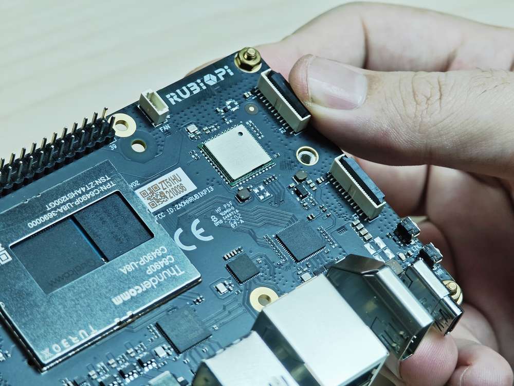
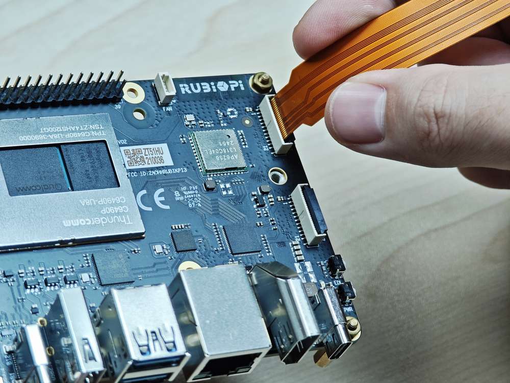
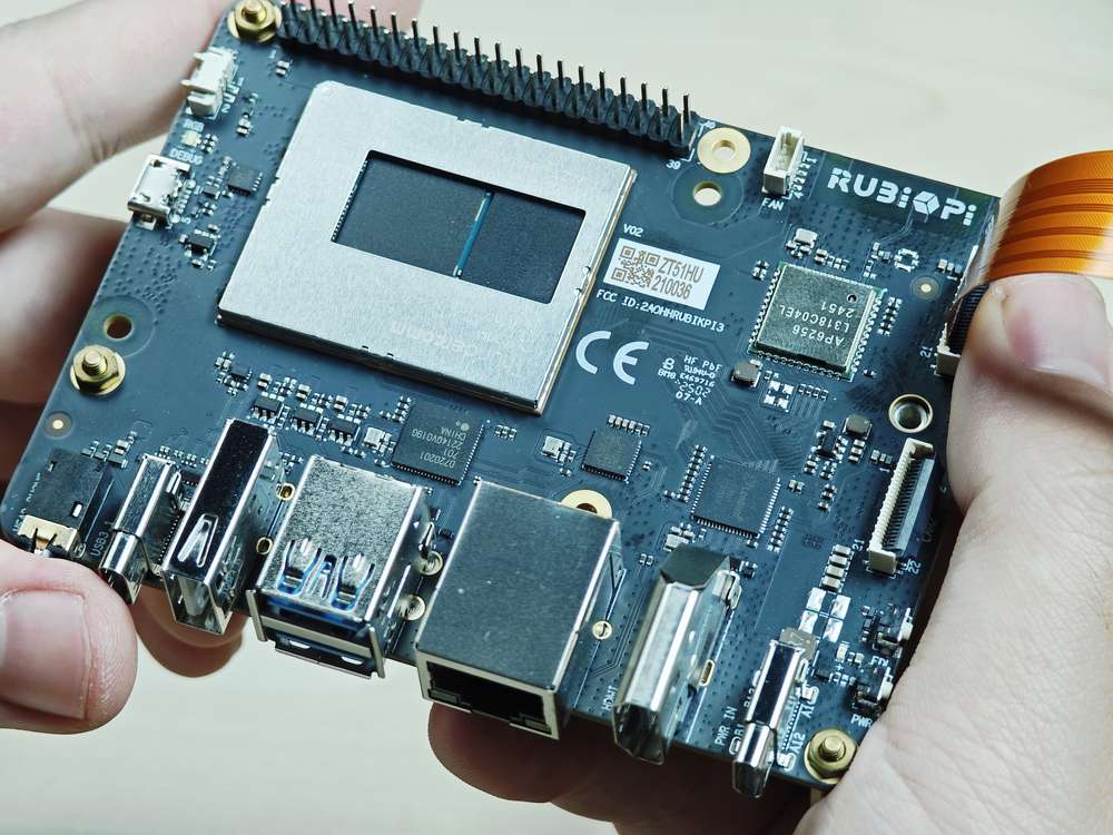
摄像头排线安装
魔方派 3 支持的摄像头 FPC 为 22 pin,0.5mm 间距,厚度 0.3±0.05mm。可以兼容 树莓派 5 同规格摄像头FPC。
严禁在板子未断电的情况下插拔摄像头,否则非常容易烧坏摄像头模组。

-
向上拉开连接器的锁扣部分:
-
插入 FPC,注意接触面朝向板内:
-
按下锁扣,确认 FPC 稳定没有松动:
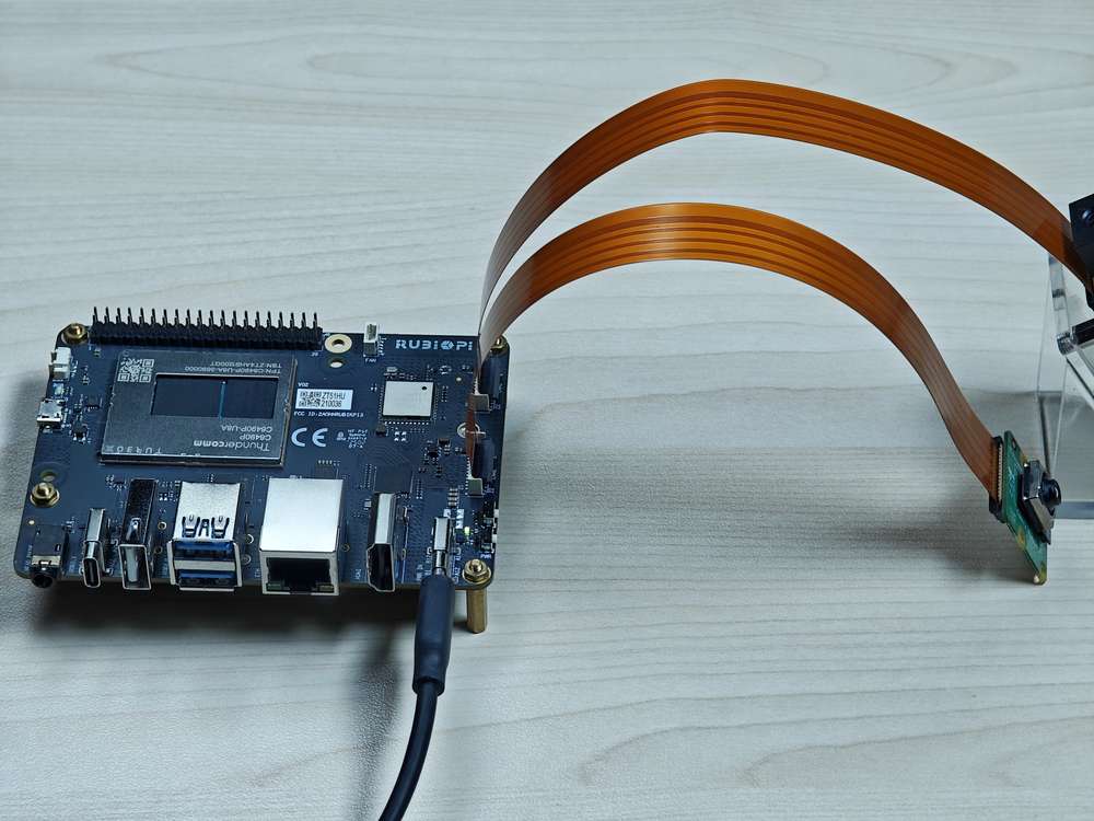
摄像头使用方法
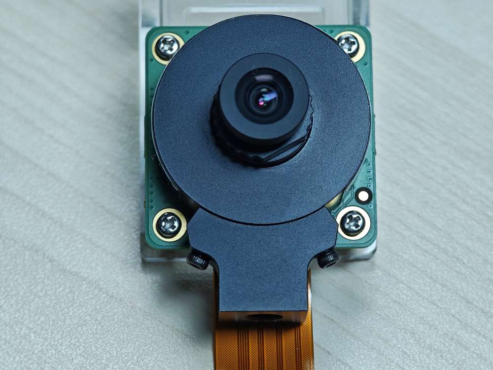
将摄像头插入,下图 13 和 14 处

如下为实物连接图:
暂时无法支持两个 IMX708 在4608x2592 分辨率下同时运行。
- 录像
通过 ADB 方式登陆到 魔方派 3
adb shell
su # 切换到root 用户,开启命令补全
在魔方派 3 中执行如下命令录像
export GST_PLUGIN_PATH=/usr/lib/gstreamer-1.0/:$GST_PLUGIN_PATH
export LD_LIBRARY_PATH=/usr/lib
gst-launch-1.0 -e qtiqmmfsrc camera=0 name=camsrc video_0::type=preview ! video/x-raw\(memory:GBM\),format=NV12,width=1920,height=1080,framerate=30/1,compression=ubwc,interlace-mode=progressive,colorimetry=bt601 ! queue ! v4l2h264enc capture-io-mode=5 output-io-mode=5 ! queue ! h264parse ! mp4mux ! queue ! filesink location="/opt/mux0.mp4"
视频保存为 /opt/mux0.mp4。
- 拍照
通过 ADB 方式登陆到 魔方派 3
adb shell
su # 切换到root 用户,开启命令补全
在魔方派 3 中执行如下命令拍照
export GST_PLUGIN_PATH=/usr/lib/gstreamer-1.0/:$GST_PLUGIN_PATH
export LD_LIBRARY_PATH=/usr/lib
gst-launch-1.0 -e qtiqmmfsrc camera=0 name=qmmf ! image/jpeg,width=1920,height=1080,framerate=30/1 ! multifilesink location=/opt/frame%d.jpg sync=true async=false max-files=2
拍照完成后在 /opt 目录下会生成对应的 frame%d.jpg 文件,如下图:
摄像头故障排除
如果摄像头无法显示或捕捉图像,请检查以下内容:
-
检查摄像头模块连接
请参阅 摄像头排线安装。
-
运行单流预览用例
export XDG_RUNTIME_DIR=/dev/socket/weston
export WAYLAND_DISPLAY=wayland-1
setprop persist.overlay.use_c2d_blit 2
gst-launch-1.0 -e qtiqmmfsrc camera=0 name=camsrc ! video/x-raw\(memory:GBM\),format=NV12,width=1920,height=1080,framerate=30/1,compression=ubwc ! queue ! waylandsink sync=false x=1000 y=1000 width=960 height=540 enable-last-sample=false -
使用以下命令收集日志
journalctl -f > /opt/log.txt在日志中搜索 "probe success" 。Probe success 意味着摄像头模块已通电并响应 I2C 控制。如果特定传感器没有 "probe success" 日志,则可能是柔性电缆连接或摄像头模块的问题。
以下日志指示探测到一个 IMX477:
[ 80.645992] CAM_INFO: CAM-SENSOR: cam_sensor_driver_cmd: 939: Probe success,slot:7,slave_addr:0x34,sensor_id:0x477, is always on: 0 -
检查摄像头传感器驱动程序命令
使用
journalctl -f > /opt/log.txt命令收集日志并搜索 "cam_sensor_driver_cmd" 。"CAM_START_DEV Success" 表示摄像头传感器流式传输开始。"CAM_STOP_DEV Success" 表示摄像头传感器流式传输停止。例如:
start:
[   81.172814] CAM_INFO: CAM-SENSOR: cam_sensor_driver_cmd: 1129: CAM_START_DEV Success, sensor_id:0x477,sensor_slave_addr:0x34
stop:
[ 88.905241] CAM_INFO: CAM-SENSOR: cam_sensor_driver_cmd: 1157: CAM_STOP_DEV Success, sensor_id:0x477,sensor_slave_addr:0x34 -
检查传感器流式传输
启用 CSID SOF/EOF IRQ 日志,随后执行摄像头出流命令
mount -o rw,remount /usr
mount -t debugfs none /sys/kernel/debug/
echo 0x8 > /sys/module/camera/parameters/debug_mdl
echo 3 >/sys/kernel/debug/camera_ife/ife_csid_debug
echo 1 > /sys/kernel/tracing/tracing_on
echo 1 > /sys/kernel/tracing/events/camera/cam_log_debug/enable
echo 2 > /sys/module/camera/parameters/debug_type
cat /sys/kernel/tracing/trace_pipe > trace.txt
捕获的日志有助于提供有关 SOF 和 EOF 的详细信息。在日志 "trace.txt" 中搜索 "irq_status_ipp"。
-
BIT12(0x1000)表示 SOF 数据包
-
BIT9(0x200)表示 EOF 数据包。
日志如下所示:
<idle>-0       [000] d.h1. 19287.546764: cam_log_debug:
CAM_DBG: CAM-ISP: cam_ife_csid_irq: 4996: irq_status_ipp = 0x1110 cam-server-25604     [000] dNH.. 19287.561705: cam_log_debug:
CAM_DBG: CAM-ISP: cam_ife_csid_irq: 4996: irq_status_ipp = 0xee8 -
HDMI OUT
魔方派 3 的 HDMI 接口为下图 9。
魔方派 3 HDMI 参数信息:
-
HDMI 1.4
-
3840 x 2160 分辨率 @ 30 fps
-
DSI 0 to HDMI (LT9611)
-
支持 CEC
-
支持分辨率自适应
-
支持热插拔

DP 和 HDMI 可同时接显示器,并发显示。
CEC
HDMI CEC(Consumer Electronics Control��,消费者电子控制)是 HDMI 标准中的一项功能,旨在通过单一的 HDMI 连接线实现多设备之间的互联与统一控制。具体来说,CEC 允许连接的设备通过专用的 CEC 引脚进行通信,从而实现例如通过一个遥控器控制多台设备的功能。
使用下面命令 安装 cec-client 工具。
sudo apt install cec-utils
将 HDMI 线连接到电视后,可使用下面命令查看电视是否支持 CEC:
echo 'scan' | cec-client -s -d 1
若支持 CEC 将会有如下输出:
opening a connection to the CEC adapter...
requesting CEC bus information ...
CEC bus information
===================
device #0: TV
address:       0.0.0.0
active source: no
vendor:        Sony
osd string:    TV
CEC version:   1.4
power status:  standby
language:      eng


device #1: Recorder 1
address:       1.0.0.0
active source: no
vendor:        Pulse Eight
osd string:    CECTester
CEC version:   1.4
power status:  on
language:      eng


device #4: Playback 1
address:       3.0.0.0
active source: no
vendor:        Sony
osd string:    PlayStation 4
CEC version:   1.3a
power status:  standby
language:      ???
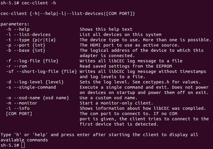
若电视支持 CEC 功能,可在魔方派 3 中使用下面命令控制电视音量的加减:
echo 'volup' | cec-client -t p -s
echo 'voldown' | cec-client -t p -s
更多 cec-client 使用方法,可使用 -h 参数进行查看:
HDMI OUT 触摸屏
魔方派 3 默认支持 1024*600P 分辨率的 HDMI OUT 触摸屏,如下图所示:
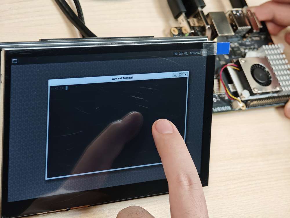
上图中使用的屏幕为 7 寸 IPS 高清触摸屏幕。
HDMI OUT 调试
魔方派 3 使用的是 LT9611 这款 DSI-to-HDMI 桥接芯片。
下表列 HDMI 桥接芯片所需的配置。
| 说明 | DTSI 节点 |
|---|---|
| 将 DSI-to-HDMI 桥接面板设置为 Primary | &sde_dsi { qcom, dsi-default-panel = <&dsi_ext_bridge_1080p>; |
| 为桥接芯片配置基准电源条目 | &sde_dsi { vddio-supply = <&vreg_18c_ip62>; vdda-9p9-supply = <&vreg_11oc_9p88>; vdda-9p9-supply = <&vreg_11oc_9p88>; |
| 为桥接芯片配置面板复位 GPIO | lt9611: lt,lt9611 { reset-options = <&tlmm 21 0>;} |
| 在外部桥接模式下配置 DSI 主机驱动程序以使用第三方 DSI-to-HDMI 桥接芯片 | qcom,mdss-dsi-ext-bridge-mode; |
下面命令需切换到 root 用户。执行
su root命令,换到 root 用户
帐号: root
密码: root
获取 lt9611 日志
要获取 LT9611 日志,请运行以下命令:
dmesg | grep lt9611
查看 log,出现下面的字样代表 HDMI OUT 可以正常运行。
这段日志记录了 LT9611 芯片的初始化和 HDMI 连接过程,从固件版本检测到 CEC 初始化,芯片启动正常。
-
芯片的固件版本是 0xe2.17.02。这表示芯片初始化时,驱动成功读取了版本信息。
-
LT9611 的 CEC(消费电子控制)功能适配器成功注册。
-
CEC 初始化完成,表明 LT9611 的 CEC 模块已经可以正常工作。
-
芯片成功读取了 HPD(热插拔检测)状态,并且会有返回值,表示确认 HDMI 设备接入。
-
芯片检测到视频信号参数:水平分辨率 1920(像素),垂直分辨率 1080(像素),像素时钟频率 148500 kHz(148.5 MHz)。这对应的是 1080p 分辨率(全高清),60Hz 刷新率的典型配置。
[    5.492765] lt9611 9-0039: LT9611 revision: 0xe2.17.02
[    5.570258] lt9611 9-0039: CEC adapter registered
[    5.582944] lt9611 9-0039: CEC init success

[    8.233028] lt9611 9-0039: success to read hpd status: 13
[    8.233044] lt9611_device_connect_status_notify: send msg[Hdmi Connection] ret[32]
[    8.345015] lt9611 9-0039: hdisplay=1920, vdisplay=1080, clock=148500
[    8.836662] lt9611 9-0039: video check: hactive_a=1920, hactive_b=1920, vactive=1080, v_total=1125, h_total_sysclk=401, mipi_video_format=170
获取 DSI 日志
我们也可以通过输出的 DSI 信息进行调试,DSI 指的是 Display Serial Interface(显示串行接口),通常与移动设备或嵌入式系统的显示驱动(如 MIPI DSI)相关。
这个命令用来查看与显示接口(DSI)相关的内核日志,通常用于调试显示驱动或硬件问题。
dmesg | grep dsi
输出结果示例:
[    4.811430] i2c 9-0039: Fixed dependency cycle(s) with /soc@0/qcom,dsi-display-primary
[    4.941131] dsi_phy ae94400.qcom,mdss_dsi_phy0: supply gdsc not found, using dummy regulator
[    4.941385] [drm:dsi_pll_init [msm_drm]] [msm-dsi-info]: DSI_PLL_0: DSI pll label = dsi_pll_5nm
[    4.941466] [drm:dsi_pll_init [msm_drm]] [msm-dsi-info]: DSI_PLL_0: PLL SSC enabled
[    4.941513] dsi_pll_init: PLL base=00000000625eaee4
[    4.941658] [drm:dsi_pll_clock_register_5nm [msm_drm]] [msm-dsi-info]: DSI_PLL_0: Registered clocks successfully
[    4.941700] [drm:dsi_phy_driver_probe [msm_drm]] [msm-dsi-info]: DSI_0: Probe successful
[    4.973185] [drm:dsi_ctrl_dev_probe [msm_drm]] [msm-dsi-info]: dsi-ctrl-0: Probe successful

[    5.585113] [drm:dsi_display_bind [msm_drm]] [msm-dsi-info]: Successfully bind display panel 'qcom,mdss_dsi_ext_bridge_1080p '
[    5.585154] msm_drm ae00000.qcom,mdss_mdp0: bound soc@0:qcom,dsi-display-primary (ops dsi_display_comp_ops [msm_drm])
[    8.345467] [drm:dsi_display_set_mode [msm_drm]] [msm-dsi-info]: mdp_transfer_time=0, hactive=1920, vactive=1080, fps=60, clk_rate=0
[    8.345740] [drm:dsi_ctrl_isr_configure [msm_drm]] [msm-dsi-info]: dsi-ctrl-0: IRQ 249 registered
获取显示面板信息
若要查看选定的显示面板,请运行以下命令:
cat /sys/kernel/debug/qcom,mdss_dsi_ext_bridge_2k60/dump_info
示例输出
name = qcom,mdss_dsi_ext_bridge_2k60
        Resolution = 2560(80|48|32|1)x1440(33|3|5|1)@60fps 0 Hz
        CTRL_0:
                ctrl = dsi-ctrl-0
                phy = dsi-phy-0
        Panel = ext video mode dsi bridge
        Clock master = dsi-ctrl-0
获取 DSI 时钟信息
若要检查 DSI 时钟信息,请运行以下命令:
cat /sys/kernel/debug/qcom,mdss_dsi_ext_bridge_2k60/dsi-ctrl-0/state_info
示例输出
Current State:
        CTRL_ENGINE = ON
        VIDEO_ENGINE = ON
        COMMAND_ENGINE = OFF

Clock Info:
        BYTE_CLK = 181274400, PIXEL_CLK = 241699200, ESC_CLK = 19200000
获取调压器信息
要检查调压器状态和电压,请运行以下命令:
cat /sys/kernel/debug/regulator/regulator_summary
获取接口信息
要检索调试 dump 输出(显示接口编号、VSync 计数、欠载计数和接口模式),请运行以下命令:
cat /sys/kernel/debug/dri/0/encoder*/status
示例输出
intf:1    vsync:  359036     underrun:       0    mode: video
intf:0    vsync:       0     underrun:       0    mode: video
获取常规 DPU 调试信息
常见的 DPU 调试信息说明如下:
要检查 DPU 时钟速率,请运行以下命令:
cat /sys/kernel/debug/clk/clk_summary | grep disp_cc
将 DPU 设置为性能模式
cd /sys/kernel/debug/dri/0/debug/core_perf/
echo 1 > perf_mode
DisplayPort
魔方派 3 拥有 1 个 USB Type-C 接口的 DisplayPort,如下图 5。
DP 的参数如下:
-
3840 × 2160 分辨率 @ 60 fps
-
单流传输 (Single stream transport)
-
DisplayPort 和 USB 3.0 的并发功能

DP 和 HDMI 可同时接显示器,并发显示。
DP 调试
获取 DP 日志
下面命令需切换到 root 用户。执行
su root命令,换到 root 用户
帐号: root
密码: root
输入下面命令开启日志打印权限。
echo 8 > /proc/sys/kernel/printk
echo ‘file dsi* +p’ > /sys/kernel/debug/dynamic_debug/control
第一条命令中的
8表示日志级别。Linux 内核用 0 到 8 表示日志的优先级,数值越小,优先级越高:
0 (KERN_EMERG): 系统紧急情况(比如崩溃)。
1 (KERN_ALERT): 需要立即处理的问题。
2 (KERN_CRIT): 严重错误。
3 (KERN_ERR): 一般错误。
4 (KERN_WARNING): 警告。
5 (KERN_NOTICE): 正常但值得注意的事件。
6 (KERN_INFO): 信息性消息。
7 (KERN_DEBUG): 调试信息。
8: 比调试�还低的级别,可以打出全部级别。
而echo ‘file dsi* +p’ > /sys/kernel/debug/dynamic_debug/control则会显示
内核中所有文件名以 dsi* 开头的源文件(通常是 DSI 显示驱动相关的代码)里的调试信息。
这些调试信息会输出到内核日志,可以通过 dmesg 查看。通过下面的命令输出来调试 DP:
mount -t debugfs none /sys/kernel/debug
echo 'file dp_display.c +p' > /sys/kernel/debug/dynamic_debug/control
echo 'file dp_aux.c +p' > /sys/kernel/debug/dynamic_debug/control
echo 'file dp_link.c +p' > /sys/kernel/debug/dynamic_debug/control
echo 'file dp_power.c +p' > /sys/kernel/debug/dynamic_debug/control
echo 'file dp_ctrl.c +p' > /sys/kernel/debug/dynamic_debug/control
echo 'file dp_parser.c +p' > /sys/kernel/debug/dynamic_debug/control
打开全部的限制等级之后,我们就可以筛选 DP 的�日志来进行进一步的验证,以下是 DP 正常启动之后,正常启动全输出的日志:
hub 4-0:1.0: USB hub found
hub 4-0:1.0: 1 port detected
usb usb5: We don't know the algorithms for LPM for this host, disabling LPM.
hub 5-0:1.0: USB hub found
hub 5-0:1.0: 1 port detected
[drm:dp_power_clk_enable][msm-dp-info][3216]core:on link:off strm0:off strm1:off
[drm:dp_display_host_init][msm-dp-info][3216][OK]
[drm:dp_display_host_ready][msm-dp-info][2912][OK]
[drm:dp_panel_read_sink_caps][msm-dp-info][2912]fec_en=0, dsc_en=0, widebus_en=0
[drm:dp_link_process_request][msm-dp-info][2912]event: DP_LINK_STATUS_UPDATED
[drm:dp_power_clk_enable][msm-dp-info][2912]core:on link:on strm0:off strm1:off
[drm:dp_catalog_ctrl_fec_config][msm-dp-err][2912]no link
[drm:dp_ctrl_link_train][msm-dp-info][2912]link training #1 successful
[drm:dp_ctrl_link_train][msm-dp-info][2912]link training #2 successful
[drm:dp_link_process_request][msm-dp-info][2912]event: DP_LINK_STATUS_UPDATED
[drm:dp_catalog_ctrl_fec_config][msm-dp-err][2912]no link
[drm:dp_ctrl_link_train][msm-dp-info][2912]link training #1 successful
[drm:dp_ctrl_link_train][msm-dp-info][2912]link training #2 successful
[drm:dp_display_send_hpd_event][msm-dp-info][2912][name=DP-1]:[status=connected] [bpp=0] [pattern=0]
[drm:dp_display_send_hpd_event][msm-dp-info][2912]uevent success: 0
lt9611 9-0039: success to read hpd status: 8
lt9611_device_connect_status_notify: send msg[Hdmi Disconnect] ret[32]
lt9611 9-0039: success to read hpd status: 8
lt9611_device_connect_status_notify: send msg[Hdmi Disconnect] ret[32]
[drm:dp_power_clk_enable][msm-dp-info][577 ]core:on link:on strm0:on strm1:off
[drm:dp_catalog_ctrl_fec_config][msm-dp-err][577 ]no link
[drm:dp_ctrl_link_train][msm-dp-info][577 ]link training #1 successful
[drm:dp_ctrl_link_train][msm-dp-info][577 ]link training #2 successful
[drm:dp_panel_resolution_info][msm-dp-info][577 ]DP RESOLUTION: active(back|front|width|low)
[drm:dp_panel_resolution_info][msm-dp-info][577 ]1920(148|88|44|0)x1080(36|4|5|0)@60fps 24bpp 148500Khz 10LR 2Ln
以上正常启动流程的日志总结如下:
-
USB 初始化: 系统启动时检测到两个单端口 USB HUB,禁用 USB 5 的 LPM。
-
DP 准备: DP 控制器初始化,读取显示器能力,准备建立连接。
-
DP 链接训练: 通过多次链接训练,DP 与显示器建立稳定连接。
-
DP 连接确认: 系统确认 DP-1 已连接,通知用户空间。
-
HDMI 断开: LT9611 检测到 HDMI 断开,可能是用户操作或接口切换。
-
DP 输出: HDMI 断开后,DP 启用视频流,输出 1080p@60Hz 的画面。
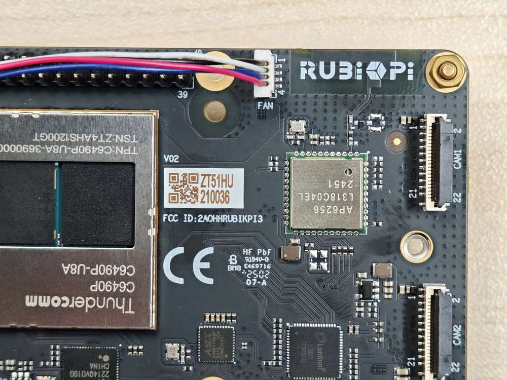
Wi-Fi & 蓝牙
魔方派 3 上搭载了AP6256 Wi-Fi 模块,支持 Wi-Fi 5 和蓝牙 5.2�。
Wi-Fi
Wi-Fi 是一种使用 IEEE 802.11 协议的无线网络技术。它允许智能手机、可穿戴设备、笔记本电脑、台式机和其他消费电子产品等电子设备在没有物理电缆的情况下连接到互联网。
工作频段
AP6256 Wi-Fi 模块支持 2.4 GHz、5 GHz 工作频段。
工作模式
Wi-Fi 是一种使用 IEEE 802.11 协议的无线网络技术。它允许智能手机、可穿戴设备、笔记本电脑、台式机和其他消费电子产品等电子设备在没有物理电缆的情况下连接到互联网。
Wi-Fi 软件在以下模式下运行:
| 模式 | 说明 |
|---|---|
| STA 模式 | 在 STA 模式下,设备连接到 Wi-Fi 网络中的接入点,并与网络中的其他设备进行通信。此模式是 Wi-Fi 连接中的无线设备的标准模式。 |
| 热点模式 | 热点模式使设备能够使用蜂窝链路 (LTE) 向 Wi-Fi 客户端提供回程 (Internet) 连接。该设备通过其轻量级热点接口建立此连接。在热点模式下,设备可以:与连接到同一热点的其他 Wi-Fi 客户端通信。与热点设备通信。共享设备的 WAN 连接。 |
STA 模式
在 STA 模式(Station)下,设备可连接到一个已经存在的无线网络,以便访问网络资源或互联网。
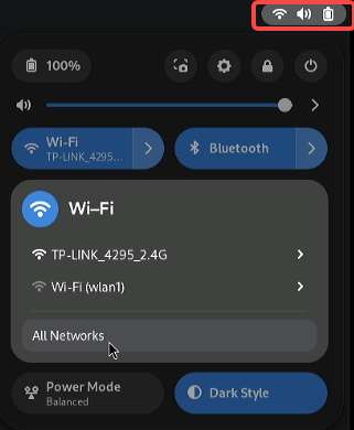
- 在用户界面连接
在魔方派 中,连接显示器,点击桌面右上角的图标,在弹出的窗口中点 Wi-Fi 图标,按照提示连接对应的 Wi-Fi。 Wi-Fi 连接成功后,会在右上角显示 Wi-Fi 图标,如下所示。
- 使用命令行连接
- 使用命令扫描 Wi-Fi
nmcli dev wifi list 2>&1 | less
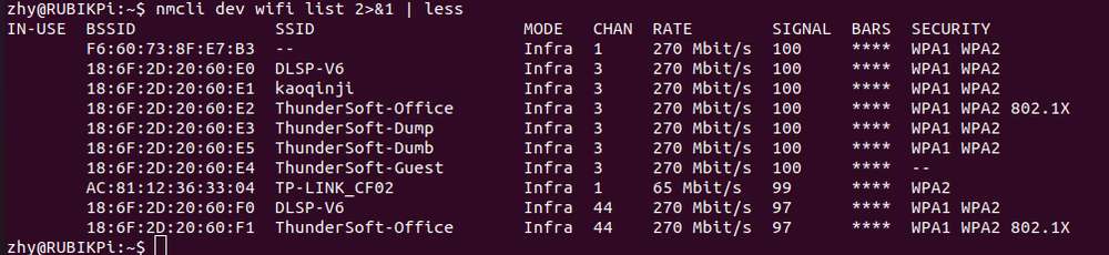
按下
q退出
- 使用命令连接 Wi-Fi
sudo nmcli dev wifi connect <WiFi-SSID> password <WiFi-password>
例如,运行命令
sudo nmcli dev wifi connect rubikpiwifi password 123456789
其中,Wi-Fi SSID 为 rubikpiwifi,Wi-Fi 密码为 123456789。
示例输出
Device 'wlan0' successfully activated with 'e8b98f24-3f23-4742-8aa3-0d37c5ee6564'.
如果您在运行命令时看到网络错误消息,请运行以下命令之一来触发 Wi-Fi 扫描并验证目标 AP。
nmcli dev wifi list
iw dev wlan0 scan
- 要查看连接状态,请运行以下命令:
nmcli general status
示例输出
STATE  CONNECTIVITY  WIFI-HW  WIFI    WWAN-HW  WWAN
connected  full     enabled  enabled  enabled  enabled
-
要验证连接状态,请执行以下步骤:
- 要查看设备状态,请运行以下命令:
nmcli dev status示例输出
DEVICE  TYPE      STATE        CONNECTION
wlan0   wifi      connected    RUbikpiWiFi
eth0    ethernet  unavailable  --
eth1    ethernet  unavailable  --
can0    can       unmanaged    --
lo loopback unmanaged --- 要查看附加连接信息,请运行以下命令:
nmcli device show wlan0示例输出
GENERAL.DEVICE:                         wlan0
GENERAL.TYPE:                           wifi
GENERAL.HWADDR:                         00:03:7F:12:F7:F7
GENERAL.MTU:                            1500
GENERAL.STATE:                          100 (connected)
GENERAL.CONNECTION:                     QualcommWiFi
GENERAL.CON-PATH:                       /org/freedesktop/NetworkManager/ActiveConnection/5
IP4.ADDRESS[1]:                         192.168.117.130/24
IP4.ADDRESS[2]:                         192.168.117.131/24
IP4.GATEWAY: 192.168.117.126- 通过在 UART 控制台中运行 ifconfig wlan0 命令来验证是否在 wlan0 接口上分配了 IP 地址
ifconfig wlan0- 通过 ping 以下公共 DNS IP:验证 AP 或路由器是否已连接至 Internet
ping 8.8.8.8
如果您已连接至一个网络,但想要使用另一连接,则可以通过指定 SSID
nmcli con down ssid/uuid将连接切换为关闭来断开连接。或者,如果您有多个具有相同 SSID 的连接,请使用 UUID。要连接到另一个已保存的连接,只需运行以下命令来传递
nmcli命令行工具中的 up 选项即可。nmcli con up ssid/uuid
要退出标准输入 shell,请按 CTRL+C。
有关 nmcli 的更多信息,请参阅 https://www.linux.org/docs/man1/nmcli.html 和 https://networkmanager.dev/docs/api/latest/nmcli.html
热点模式
AP 模式(Access Point)即无线接入热点模式,是一个无线网络的创建者,是网络的中心节点,一般家庭或办公室使用的无线网络路由器就是一个 AP,下面是 AP 的创建步骤:
-
开启 AP
-
创建或修改 /opt/hostapd.conf 文件:
ctrl_interface=/var/run/hostapd
driver=nl80211
ieee80211n=1
interface=wlan1
hw_mode=a
channel=36
beacon_int=100
dtim_period=1
ssid=RUBIKPi
auth_algs=1
ap_isolate=0
ignore_broadcast_ssid=0
wpa=2
wpa_key_mgmt=WPA-PSK
rsn_pairwise=CCMP
wpa_passphrase=123456789 -
执行下面命令开启 AP:
hostapd -B /opt/hostapd.conf # 设置软件AP
# 启动动态主机配置协议(DHCP)服务器
brctl addbr br0
brctl addif br0 wlan1
ifconfig br0 192.168.225.1 netmask 255.255.255.0 up
killall dnsmasq
dnsmasq --conf-file=/etc/dnsmasq.conf --dhcp-leasefile=/var/run/dnsmasq.leases --addn-hosts=/data/hosts --pid-file=/var/run/dnsmasq.pid -i br0 -I lo -z --dhcp-range=br0,192.168.225.20,192.168.225.60,255.255.255.0,43200 --dhcp-hostsfile=/data/dhcp_hosts --dhcp-option-force=6,192.168.225.1 --dhcp-script=/bin/dnsmasq_script.sh -
若要与 hostapd_cli 建立连接,可使用下面命令
hostapd_cli -i wlan1 -p /var/run/hostapd
在
hostapd_cli控制台中监视 Wi-Fi STA 连接通知,例如AP-STA-CONNECTED、EAPOL-4WAY-HS-COMPLETED示例输出
root@rubikpi:~# hostapd_cli -i wlanl -p /var/run/hostapd
hostapd_cli v2.11-devel
Copyright (c) 2004-2022, Jouni Malinen <j@wl.fi> and contributors
This software may be distributed under the terms of the BSD License.
See README for more details.

Interactive mode
> <3>AP-STA-CONNECTED aa: a4: fd: 8b: ec: 90
<3>EAPOL-4WAY-HS-COMPLETED aa: a4: fd: 8b:ec:90

> list_sta
aa: a4: fd: 8b:ec:90 -
若开启 AP 5G 模式前,未使用 STA 连接过 5G Wi-Fi,则需使用如下命令,查看环境中 5G channel 的配置
iw dev wlan0 scan
在命令执行结果中通过,primary channel 字段确定当前已被激活 channel,如下所示,channel 字段为 36,将36 写入 /opt/hostapd.conf 文件中的 channel 字段即可
HT operation:
                * primary channel: 36
                * secondary channel offset: above
                * STA channel width: any
                * RIFS: 0
                * HT protection: nonmember
                * non-GF present: 0
                * OBSS non-GF present: 0
                * dual beacon: 0
                * dual CTS protection: 0
                * STBC beacon: 0
                * L-SIG TXOP Prot: 0
                * PCO active: 0
                * PCO phase: 0
-
验证 AP
要验证连接状态,请从其他设备连接到 AP。
例如,通过执行以下步骤从移动设备连接到 AP:
-
在移动设备上,转到 Wi-Fi settings。
-
等待 Wi-Fi STA 检测到 AP。
-
选择 AP 并输入在魔方派 3 设备上为 AP 配置的相应
wpa_passphrase,然后进行连接。
> status
state=ENABLED
phy=phyR freq=2412
num_sta_non_erp=0
num_sta_no_short_slot_time=0
num_sta_no_short_preamble=0
olbc=0
num_sta_ht_no_gf=0 num_sta_no_ht=0
num_sta_ht_20_mhz=0
num_sta_ht40_intolerant=0
olbc_ht=0
ht_op_mode=0x0
hw_mode=g
country_code=US
country3=0x20
cac_time_seconds=0
cac_time_left_seconds=N/A
channel=1
edmg_enable=0 edmg_channel=0
secondary_channel=0
ieee80211n=1
ieee80211ac=0
ieee80211ax=0
ieee80211be=0
beacon_int=100
dtim_period=2
ht_caps_info=000c
ht_mcs_bitmask=ffff0000000000000000
supported_rates-02 04 0b 16 Oc 12 18 24 30 48 60 6c
max_txpower=30
bss[0]=wlan1
bssid[0]=00:03:7f:95:8e:8e
ssid [0]=QSoftAP
num_sta[0]=1
> |
要验证连接,在魔方派 3 设备的
ssh shell中 ping 移动设备的 IP 地址。以下输出表示 Wi-Fi 连接已成功建立,数据传输已开始:
sh-5.1# ping 192.168.1.42
PING 192.168.1.42 (192.168.1.42): 56 data bytes
64 bytes from 192.168.1.42: seq=0 ttl=64 time-11.175 ms
64 bytes from 192.168.1.42: seq=1 ttl=64 time=14.528 ms
64 bytes from 192.168.1.42: seq=2 ttl=64 time=29.735 ms
64 bytes from 192.168.1.42: seq=3 ttl=64 time=223.822 ms
64 bytes from 192.168.1.42: seq-4 ttl=64 time-23.675 ms
^C
192.168.1.42 ping statistics ---
7 packets transmitted, 5 packets received, 28% packet loss
round-trip min/avg/max = 11.175/60.587/223.822 ms
sh-5.1#
也可以在连接设备的 Settings 中验证 Wi-Fi 连接状态。例如,要获取连接到 魔方派 3 AP 的移动设备的 IP 地址,执行以下步骤:
-
-
导航至 Settings > Wi-Fi。
-
验证 AP 的 SSID。
- 关闭 AP:
要停止 AP,在 SSH 中执行以下操作:
-
通过执行以下步骤停止 hostapd:
-
要停止 hostapd 过程,可运行以下命令:
killall hostapd -
要禁用接口,可运行以下命令:
ifconfig wlan1 down
-
-
请运行以下命令,以便删除
ctrl_interface:rm -rf /var/run/hostapd/wlan1
Wi-Fi 热点成功停止。
蓝牙
蓝牙® 无线技术是一种短距离通信系统,可实现设备之间的无线数据交换。蓝牙技术的主要优势如下:
-
替代便携式和固定式电子设备的线缆
-
提供稳健、节能且经济高效的解决方案
-
促进解决方案及其应用的灵活性。
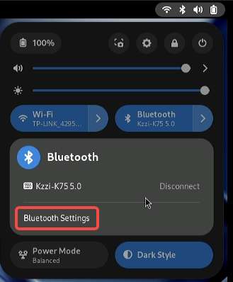
在魔方派 中,连接显示器,点击桌面右上角的图标,在弹出的窗口中点 Bluetooth 图标,点击 Bluetooth Settings 按照提示连接对应的 设备。 蓝牙连接成功后,会在右上角显示蓝牙图标,如下所示。
音频
魔方派 3 目前支持的音接口为:
-
3.5mm 耳机,下图4。
-
HDMI OUT, 下图9。
-
蓝牙

查看声卡信息
-
在魔方派 3 中输入下面命令,查看声卡挂载情况:
cat /proc/asound/cards
-
在魔方派 3 中输入下面命令,查看已分配的 pcm 流列表:
cat /proc/asound/pcm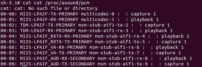
设置输出源
在魔方派 3 中输入下面命令,改变系统与应用、 gstreamer、paplay 等命令的音频输出源头:
-
设置输出接口为 3.5mm Headset
rubikpi_config audio output headset或
pactl set-sink-port low-latency0 headset -
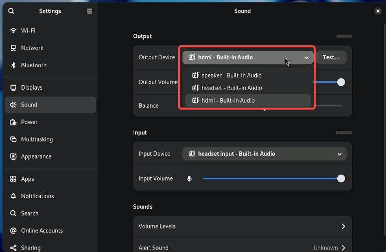
设置输出接口为 HDMI OUT
rubikpi_config audio output hdmi或
pactl set-sink-port low-latency0 hdmi -
或在系统设置中,按提示切换
播放
-
在魔方派 3 中输入下面命令测试耳机播放。
注意运行命令前,务必将 MP3 测试文件 (
<FileName>.mp3) 推送到/opt/目录下。gst-launch-1.0 filesrc location=/opt/<FileName>.mp3 ! mpegaudioparse ! mpg123audiodec ! pulsesink -
在魔方派 3 中输入下面命令测试 HDMI OUT 播放。
注意运行命令前,务必将 PCM 测试文件 (
<FileName>.wav) 推送到/opt/目录下。systemctl stop pulseaudio
agmplay /opt/<FileName>.wav -D 100 -d 100 -r 48000 -b 16 -c 2 -i MI2S-LPAIF_RXTX-RX-PRIMARY
systemctl start pulseaudio -
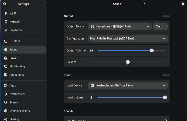
在魔方派 3 中测试蓝牙设备播放。
将蓝牙耳机连接到设备后,系统自动将音频输出源切换到蓝牙耳机,如下所示,播放音频就会从蓝牙耳机出声。
录制
在魔方派 3 中输入下面命令测试录音功能
-
耳机录制:
gst-launch-1.0 -v pulsesrc volume=10 ! audioconvert ! wavenc ! filesink location=/opt/test.wav -
蓝牙耳机录制
将蓝牙耳机连接到设备后,系统自动将音频输入源切换到蓝牙耳机,如下所示,使用应用进行录音时就会通过蓝牙耳机录制。

风扇
魔方派 3 兼容树莓派 5 的散热套件:
使用 魔方派 3 在运行一些高负载或高性能的场景下,需要使用散热措施来保证设备性能稳定,否则会因为 CPU 温度过高而带来降频等性能影响。
风扇安装
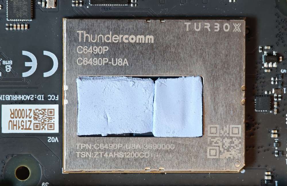
- 将散热器背面所有导热硅脂移除,将下图标记的两块硅脂按 魔方派 3 的 SoC 及 uMCP 的形状裁下。
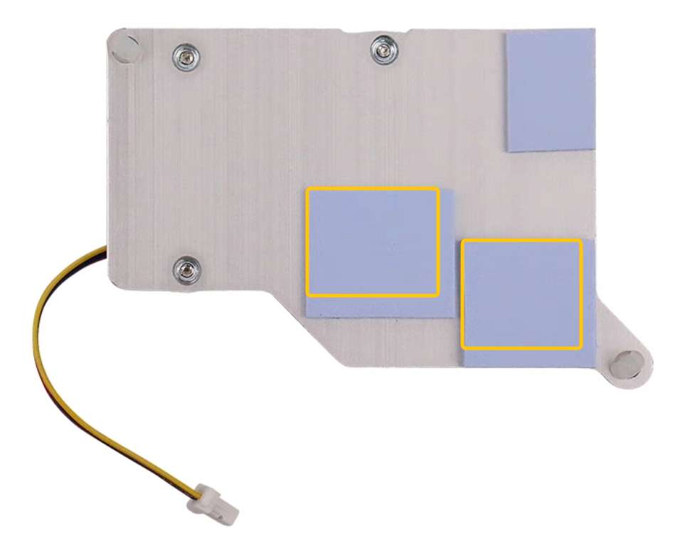
两块的表面尺寸约为14*12mm和13*11.5mm。
- 将裁剪好的两块导热硅脂贴在魔方派 3 上对应位置。
- 安装散热器,连接风扇排线。
建议将风扇安装到 魔方派 3 上后不要将其取下。拆卸会导致风扇的推针和散热垫退化,并可能导致产品损坏。如果推针损坏或变形,或无法牢固夹住,请停止使用风扇。
风扇控制方法
魔方派 3 风扇会根据当前的 CPU 温度自动调整转速,同时也可在魔方派 3 中使用下面命令进行手动控制转速,0 和 255 分别表示风扇的最高和最低速度。
rubikpi_config fan speed 100
rubikpi_config fan speed 255
rubikpi_config fan speed 0
或
echo 100 >  /sys/class/hwmon/hwmon29/pwm1
echo 255 >  /sys/class/hwmon/hwmon29/pwm1
echo 0 >  /sys/class/hwmon/hwmon29/pwm1
在将风扇转速设置为一个固定值前时,需要使用 rubikpi_config thermal disable 命令将 CPU 热管理关掉。
LED
魔方派 3 上有一个由 PMIC 驱动的 RGB 的三色灯,默认情况下其中的绿色灯被设置为了心跳灯用来反馈系统的运行情况和 CPU 负载情况(CPU 负载大时,心跳灯闪烁频率也跟着变大)。
如下是 LED 灯不同状态时,所指示的状态:
-
蓝灯长亮:fastboot 模式
-
绿色心跳:正常工作
-
红色心跳:低功耗电源插入(小于 12V 2.25A)
-
快速心跳: CPU 高负荷工作
-
停止心跳:
-
系统死机
-
进入睡眠
-
正在开机中
-
可使用如下命令,操作 LED 灯:
-
关闭心跳灯
rubikpi_config led heartbeat off或
echo none > /sys/class/leds/green/trigger -
开启心跳灯
rubikpi_config led heartbeat on或
echo heartbeat > /sys/class/leds/green/trigger -
设置绿灯的亮度(亮度 0 - 511,如下为设置亮度为100)
rubikpi_config led green 100或
echo 100 > /sys/class/leds/green/brightness -
设置红灯的亮度(亮度 0 - 511,如下为设置亮度为100)
rubikpi_config led red 100或
echo 100 > /sys/class/leds/red/brightness -
设置蓝灯的亮度(亮度 0 - 511,如下为设置亮度为100)
rubikpi_config led blue 100或
echo 100 > /sys/class/leds/blue/brightness
以太网
以太网技术旨在使用有线技术以不同的链路速度传输数据。它使用线缆在网络模型(例如局域网 (LAN) 和广域网 (WAN))中传输数据,实现可靠、安全和更出色的网络连接。
以太网连接集成到 IoT 设备和传感器,使它们能够将数据传输到网络。它根据 IEEE 802.3 标准定义,可为这些设备提供用于与网关通信的标准化接口。
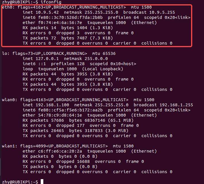
以太网接口为下图 8, 魔方派 3 支持千兆以太网:

接入网线,如下图所示:
可在魔方派 3 中使用下面命令查看网络连接情况,如下图所示,已经成功分配 IP,说明网络连接成功:
调试以太网
可以使用以下日志类型来记录和调试与以太网有关的问题。
-
dmesg:调试与内核驱动程序相关的问题 -
tcpdump: 验证数据包传输
要调试在以太网调通期间可能出现的问题,请执行以下操作:
-
要收集
dmesg日志并调试与内核驱动程序有关的问题,请运行以下命令:dmesg > /var/log/dmesg_logs.txt -
要收集
tcpdump日志并验证数据包传输,请运行以下命令。tcpdump -i any -s 0 -w /var/log/tcpdump.pcap -
收集来自
ethtool、ifconfig、netstat和 IP 路由表的输出以进行调试。
RTC 电池接口
RTC (Real_Time Clock) 电池接口为下图 1。

接入 RTC 电池, 如下图所示,并将时间写入 魔方派 3 的系统硬件时钟,可在魔方派 3 完全断电后,仍对 魔方派 3 的系统时间进行保存。
在魔方派 3 中将系统时间写入系统硬件时钟方法如下:
date -s "08:00:00 20241201" # 将系统时间设置为2024年12月1日8时0分
hwclock -w # 将系统时间写入系统硬件时钟
M.2 Key M 接口
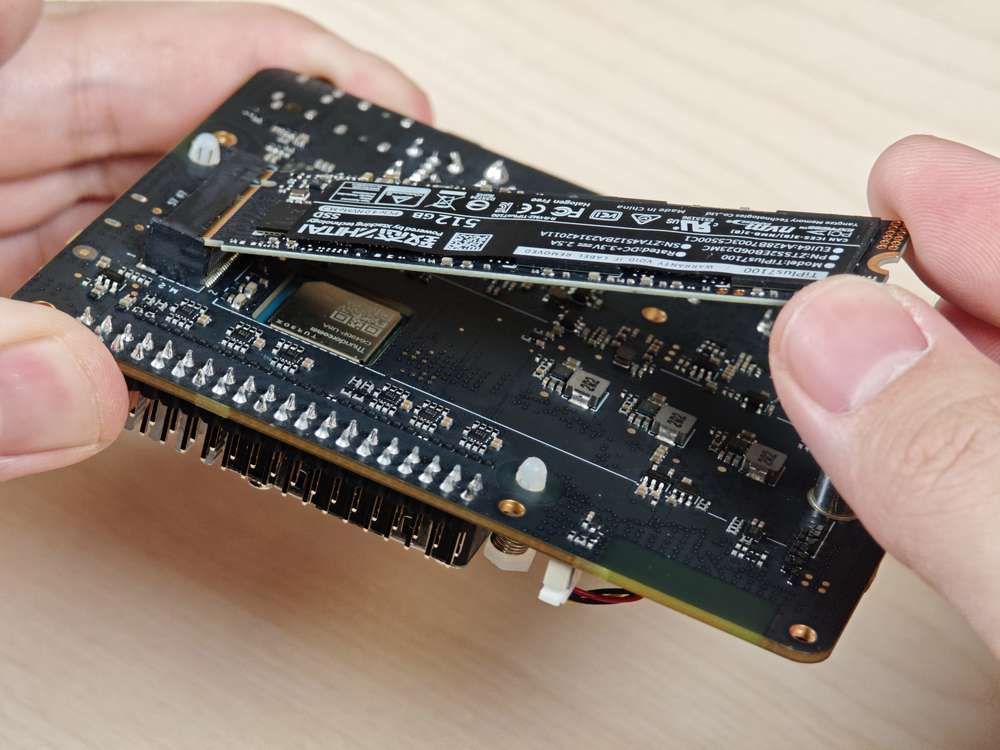
魔方派 3 提供一个标准 M.2 插槽,用于连接 NVMe 存储,可安装 2280 规格(22*80mm)M.2 SSD 硬盘。M.2 插槽最大支持 PCIe Gen 3 x 2。M.2 接口最大对外输出能力为 3.3V 2A,可单独控制开关。
M.2 Key M 接口使用了 QCS6490 的 PCIe1 总线,设备路径为:/sys/bus/pci/devices/0001:00:00.0
M.2 Key M 接口为下图 18:
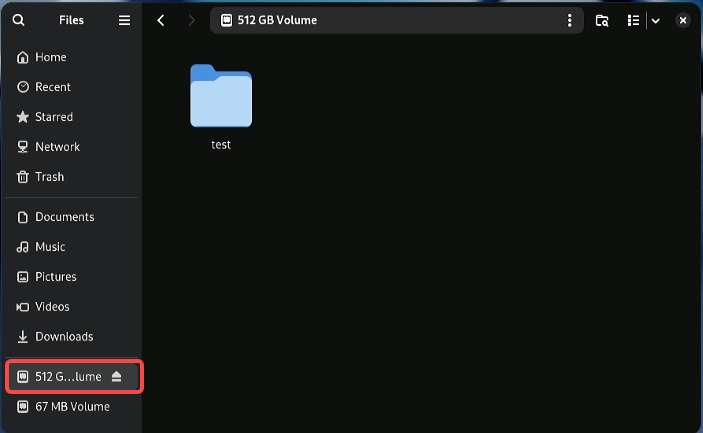
M.2 Key M 接口可以接入规格为2280的固态硬盘,如下图所示:
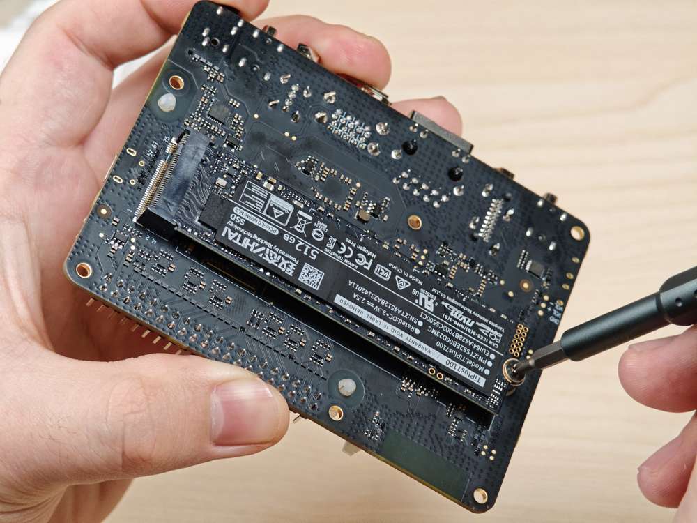
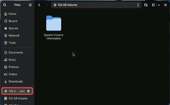
接入显示器,开机后在文件浏览器中会显示��固态硬盘,如下图所示:
PCIe 功耗优化
PCIe 定义了两种功耗管理方法。
-
功耗管理软件,用于确定每个设备的功耗管理功能并分别对各个设备进行管理
-
不需要软件干预的系统,例如主动状态功耗管理 (ASPM)
当链路上未传输任何数据包时,设备会将链路置于节能状态。
PCIe L0 链路状态
PCIe 功耗管理定义下了 L0 链路状态:
-
L0:工作状态
-
L0s:具有低恢复延迟的 ASPM 状态(节能待机状态)
PCIe 设备状态
PCIe 功耗管理定义了以下设备状态:
-
D0(必选): 设备处于完全 ON 状态,此时存在两个子状态
-
D0(uninitialized):当设备退出复位状态后等待枚举和配置时,该功能处于 D0(uninitialized) 状态
-
D0(active)
-
当完成枚举和配置过程后,该功能处于 D0(active) 状态
-
当系统软件启用一个或多个(任意组合)功能参数(如内存空间启用、I/O 空间启用、总线主启用(BME)位)时,该功能进入 D0(active) 状态
-
-
-
D1(可选):轻度休眠状态
-
该功能只能发出 PME 消息,无法发出其他 TLP
-
该功能只能充当配置事务的目标,无法充当其他事务的目标
-
该功能通过发出设定 PM 控制和状态寄存器的软件命令来进入 D1 状态
-
-
D2(可选):深度休眠状态
-
该功能只能发出 PME 消息,无法发出其他 TLP
-
该功能只能充当配置事务的目标,无法充当其他事务的目标
-
该功能通过发出设定 PM 控制和状态寄存器的软件命令来进入 D2 状态
-
-
D3(必选):设备处于最低功耗状态,此时该功能必须支持两种 D3 状态
-
D3(hot)
-
该功能只能发出 PME 消息,无法发出其他 TLP
-
该功能只能充当配置事务的目标,无法充当其他事务的目标
-
该功能通过设定功耗状态位域发出软件命令来进入 D3(hot) 状态
-
-
D3(cold):设备进入 D3(cold) 状态并断电;当恢复供电时,设备进入 D0(uninitialized) 状态
PCIe 调试
M.2 Key M 接口使用了 QCS6490 的 PCIe1 总线,设备路径为:/sys/bus/pci/devices/0001:00:00.0
lspci 和 setpci 命令为 Linux 发行版的本机命令。这两条命令提供多种级别的输出,并且还可用于在某个时间点查看 PCI 总线上训练的不同组件的功能和状态。这些功能大多反映的是 PCIe 基本规范所需的配置空间寄存器。更多详细信息,可访问 https://pcisig.com/specifications
如需查看使用说明,可运行以下命令。
lspci --help
以下功能有助于解决 PCIe 问题。
-
显示设备信息
lspci示例输出
0000:00:00.0 PCI bridge: Qualcomm Device 010b
0000:01:00.0 USB controller: Renesas Technology Corp. uPD720201 USB 3.0 Host Controller (rev 03)
0001:00:00.0 PCI bridge: Qualcomm Device 010b -
显示设备控制寄存器中的 PCIe 设备和厂商 ID。
lspci -nvmm示例输出
Slot:        00:00.0
Class:        0604
Vendor:        17cb
Device:        010b
IOMMUGroup:        6

Slot:        01:00.0
Class:        0c03
Vendor:        1912
Device:        0014
Rev:        03
ProgIf:        30
IOMMUGroup:        6

Slot:        0001:00:00.0
Class:        0604
Vendor:        17cb
Device:        010b
DTNode:        /sys/firmware/devicetree/base/soc@0/pci@1c08000/pcie@1
IOMMUGroup:        7