摄像头软件
摄像头概述
本章节介绍了通过 MIPI CSI 接口接收数据的摄像头子系统。
USB 摄像头数据通过 USB 接口传输,摄像头子系统不涉及 USB 摄像头数据传输。请参阅USB章节了解 USB 摄像头的使用。
网络摄像头数据通过网络接口传输,摄像头子系统不涉及网络摄像头数据传输。设备可以通过 GStreamer rtspsrc 插件接收网络摄像头数据。
下图显示了 Qualcomm 摄像头的组件。
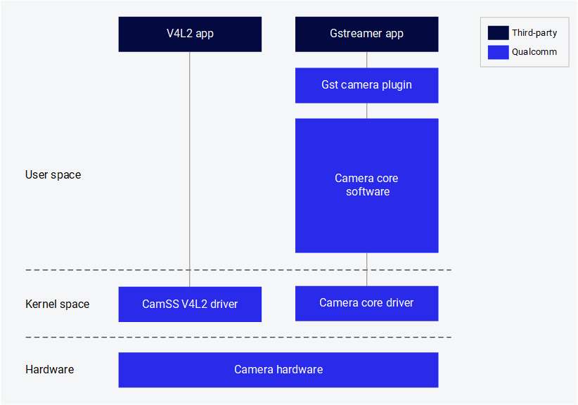
以下组件由 Qualcomm 提供:
| 组件 | 说明 |
|---|---|
| GST 摄像头插件 (qtiqmmfsrc) | Qualcomm 摄像头子系统的 GStreamer 插件 |
| 摄像头核心软件 | Qualcomm 专有的摄像头软件,提供开发摄像头传感器驱动程序、摄像头调整和自定义软件节点的接口 |
| 摄像头核心驱动程序 | 下游 Linux 内核中的 Qualcomm 摄像头子系统驱动程序 |
| CamSS V4L2 驱动程序 | 上游 Linux 内核中的 Qualcomm 摄像头子系统驱动程序 |
摄像头流传输
Qualcomm 提供了一个 GStreamer 插件,使应用程序开发者能够与 Qualcomm 摄像头子系统进行交互。
前提条件
启用显示屏:
sudo -i
systemctl stop gdm
sudo dpkg-reconfigure weston-autostart
export XDG_RUNTIME_DIR=/run/user/$(id -u ubuntu)
单摄像头流启动
- 在设备终端运行以下命令,在 30 FPS 配置下以 720p 启动摄像头。来自摄像头传感器的帧被 fakesink 丢弃。
gst-launch-1.0 -e qtiqmmfsrc name=camsrc camera=0 ! 'video/x-raw,format=NV12,\
width=1280,height=720,framerate=30/1' ! fakesink
- 如果 gst pipeline 状态更改为 “PLAYING”,如下所示,则表示摄像头正在运行。由于此命令会将摄像头帧 dump 到 fakesink,因此不会在设备上保存任何内容。
Setting pipeline to PAUSED ...
Pipeline is live and does not need PREROLL ...
Setting pipeline to PLAYING ...
New clock: GstSystemClock
视频编码
- 在设备终端运行以下命令,以 720p、30 FPS 配置启动摄像头,并在 h264 视频编码后将其另存为视频文件。
gst-launch-1.0 -e qtiqmmfsrc name=camsrc camera=0 ! \
video/x-raw,format=NV12,width=1280,height=720,framerate=30/1,\
interlace-mode=progressive,colorimetry=bt601 ! v4l2h264enc \
capture-io-mode=4 output-io-mode=5 extra-controls="controls,video_bitrate=6000000,\
video_bitrate_mode=0;" ! h264parse ! mp4mux ! filesink location=/opt/mux_avc.mp4
如果 gst pipeline 状态更改为 “PLAYING”,则表示摄像头正在运行。
- 在设备上生成
/opt/mux_avc.mp4。通过在主机 PC 上运行以下 scp 命令,可以从设备中提取录制的内容:
$ scp -r root@[ip-addr]:/opt/mux_avc.mp4 .
视频编码和拍照
- 在设备终端运行以下命令:
gst-pipeline-app -e qtiqmmfsrc name=camsrc camera=0 ! \
video/x-raw,format=NV12,width=1280,height=720,framerate=30/1,\
interlace-mode=progressive,colorimetry=bt601 ! v4l2h264enc \
capture-io-mode=4 output-io-mode=5 extra-controls="controls,video_bitrate=6000000,\
video_bitrate_mode=0;" ! h264parse ! mp4mux ! filesink location=/opt/mux_avc.mp4 \
camsrc.image_1 ! "image/jpeg,width=1280,height=720,framerate=30/1" \
! multifilesink location=/opt/frame%d.jpg async=false sync=true enable-last-sample=false
- 按下 Enter。此命令将打印以下菜单并等待用户输入。
##################################### MENU #####################################

============================== Pipeline Controls==============================
(0) NULL: Set the pipeline into NULL state
(1) READY: Set the pipeline into READY state
(2) PAUSED: Set the pipeline into PAUSED state
(3) PLAYING: Set the pipeline into PLAYING state

==================================== Other====================================
(p) Plugin Mode: Choose a plugin which to control
(q) Quit : Exit the application

Choose an option:
- 使用以下菜单步骤在录制视频时拍照。
(1) ready -> (3) Playing -> (p)Plugin Mode : Select (8)camerasrc -> (37) capture-image -> (1): still - Snapshot ->(1) Snapshot count ( 'guint' value for arg1)
- 若要停止摄像头,按 Enter,按 b(返回),然后按 q(退出)。录制的视频文件和拍照图像保存在
/opt/中。通过在主机 PC 上运行以下 scp 命令,可以从设备中提取录制的内容:
$ scp -r root@[ip-addr]:/opt/<file name> .
摄像头内容预览
gst-launch-1.0 -e qtiqmmfsrc name=camsrc video_1::type=preview ! video/x-raw,format=NV12,width=1920,height=1080,framerate=30/1,interlace-mode=progressive,colorimetry=bt601 ! waylandsink fullscreen=true sync=false
此 pipeline 显示从摄像头获取并发送到显示器的单个 1080p 流。

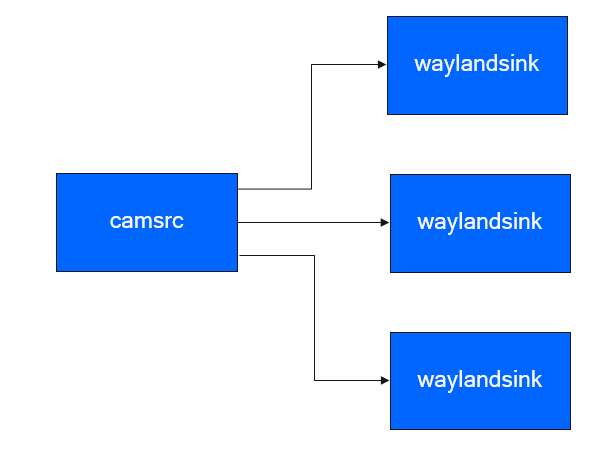
显示三路 720p YUV 视频流
gst-launch-1.0 -e qtivcomposer name=mixer sink_0::position="<0, 0>" sink_0::dimensions="<480, 270>" sink_1::position="<480, 0>" sink_1::dimensions="<480, 270>" sink_2::position="<960, 0>" sink_2::dimensions="<480, 270>" mixer. ! queue ! waylandsink fullscreen=true qtiqmmfsrc name=camsrc camera=0 video_0::type=preview video_1::type=video ! video/x-raw,format=NV12_Q08C,width=1280,height=720,framerate=30/1,interlace-mode=progressive,colorimetry=bt601 ! queue ! mixer. camsrc. ! video/x-raw,format=NV12,width=1280,height=720,framerate=30/1,interlace-mode=progressive,colorimetry=bt601 ! queue ! mixer. camsrc. ! video/x-raw,format=NV12,width=1280,height=720,framerate=30/1,interlace-mode=progressive,colorimetry=bt601 ! queue ! mixer.
该 pipeline 展示从摄像头中获取三个 720p 流并发送到显示器,每个流显示在屏幕上的不同位置。
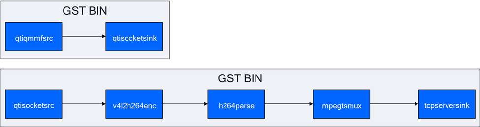
使用套接字传输摄像头流
该用例展示了如何将摄像头流存储在套接字中。然后,将套接字中的摄像头流编码为 AVC 格式并存储在文件中。
在控制台 1 中:
gst-launch-1.0 -e qtisocketsrc socket=/tmp/input.sock ! video/x-raw,format=NV12,width=1920,height=1080,framerate=30/1,interlace-mode=progressive,colorimetry=bt601 ! v4l2h264enc capture-io-mode=4 output-io-mode=5 ! h264parse ! mp4mux ! queue ! filesink location=/opt/video.mp4
在控制台 2 中:
gst-launch-1.0 -e qtiqmmfsrc name=camsrc ! video/x-raw,format=NV12,width=1920,height=1080,framerate=30/1 ! qtisocketsink socket=/tmp/input.sock
下图显示了 pipeline 执行流程:
来自实时源的 4K AVC 和 480p AVC 流
这些用例对来自摄像头的一路 4K 流和一路 1080p 流进行编码。每个编码的数据流都多路复用到不同的文件中。
gst-launch-1.0 -e qtiqmmfsrc name=camsrc video_0::type=preview ! video/x-raw,format=NV12_Q08C,width=3840,height=2160,framerate=30/1,interlace-mode=progressive,colorimetry=bt601 ! queue ! v4l2h264enc capture-io-mode=4 output-io-mode=5 ! queue ! h264parse ! mp4mux ! queue ! filesink location="/opt/mux1.mp4" camsrc. ! video/x-raw,format=NV12_Q08C,width=640,height=480,framerate=30/1,interlace-mode=progressive,colorimetry=bt601 ! queue ! v4l2h264enc capture-io-mode=4 output-io-mode=5 ! queue ! h264parse ! mp4mux ! queue ! filesink location="/opt/mux2.mp4"
下图显示了 pipeline 执行流程:
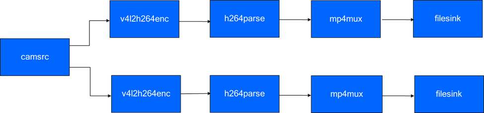
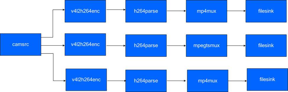
来自实时源的三个 1080p AVC 数据流
该用例对来自摄像头的三路 1080p 流进行编码。每个编码的数据流都多路复用到不同的文件中。
gst-launch-1.0 -e qtiqmmfsrc name=camsrc video_0::type=preview ! video/x-raw,format=NV12_Q08C,width=1920,height=1080,framerate=30/1,interlace-mode=progressive,colorimetry=bt601 ! queue ! v4l2h264enc capture-io-mode=4 output-io-mode=5 ! queue ! h264parse ! mp4mux ! queue ! filesink location="/opt/mux1.mp4" camsrc. ! video/x-raw,format=NV12_Q08C,width=1920,height=1080,framerate=30/1,interlace-mode=progressive,colorimetry=bt601 ! queue ! v4l2h264enc capture-io-mode=4 output-io-mode=5 ! queue ! h264parse ! mp4mux ! queue ! filesink location="/opt/mux2.mp4" camsrc. ! video/x-raw,format=NV12_Q08C,width=1920,height=1080,framerate=30/1,interlace-mode=progressive,colorimetry=bt601 ! queue ! v4l2h264enc capture-io-mode=4 output-io-mode=5 ! queue ! h264parse ! mp4mux ! queue ! filesink location="/opt/mux3.mp4"
下图显示了 pipeline 执行流程:
多摄像头显示
多摄像头/多客户端用例展示了以画中画、并排等模式显示多路摄像头视频流的场景。
- 并排拼接
- 画中画
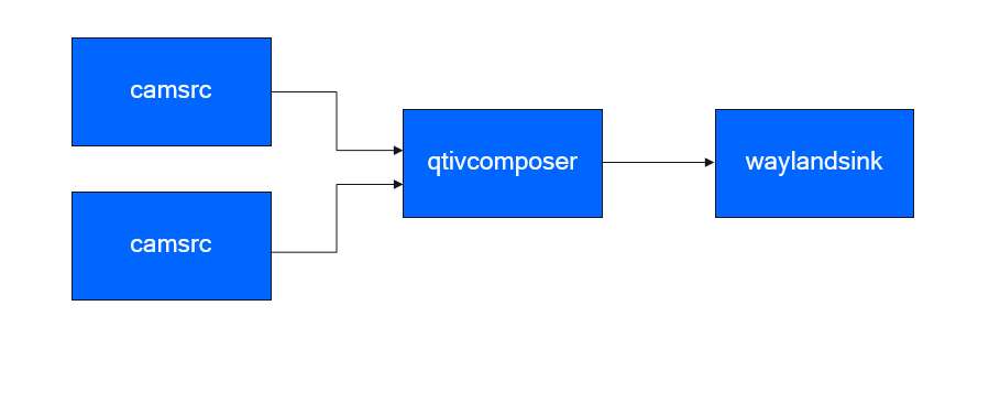
两路 720p 流 - 每个摄像头各一路,采用并排拼接方式显示
该 pipeline 展示了分别来自主摄像头和辅助摄像头的两路 720p 流。这两路流并排合成后进行显示。
gst-launch-1.0 -e qtivcomposer name=mixer sink_0::position="<0, 0>" sink_0::dimensions="<640, 360>" sink_1::position="<640, 0>" sink_1::dimensions="<640, 360>" mixer. ! queue ! waylandsink enable-last-sample=false fullscreen=true qtiqmmfsrc name=camsrc_0 camera=0 ! video/x-raw, format=NV12, width=1280, height=720, framerate=30/1 ! mixer. qtiqmmfsrc name=camsrc_1 camera=1 ! video/x-raw, format=NV12, width=1280, height=720, framerate=30/1 ! mixer.
下图显示了 pipeline 执行流程:
两路 720p 流 - 每个摄像头各一路,采用画中画合成方式
用例使用分别来自主摄像头和辅助摄像头的两路 720p 流。两者均以画中画形式组成并显示。
运行 pipeline:
gst-launch-1.0 -e qtivcomposer name=mixer sink_0::position="<0, 0>" sink_0::dimensions="<1280, 720>" sink_1::position="<590, 310>" sink_1::dimensions="<640, 360>" mixer. ! queue ! waylandsink enable-last-sample=false fullscreen=true qtiqmmfsrc name=camsrc_0 camera=0 ! video/x-raw, format=NV12, width=1280, height=720, framerate=30/1 ! mixer. qtiqmmfsrc name=camsrc_1 camera=1 ! video/x-raw, format=NV12, width=1280, height=720, framerate=30/1 ! mixer.
转换和转码
以下用例展示了调整摄像头中场景的过程。
旋转
用例展示了将摄像头中的场景旋转 180 度的过程。旋转后的图像显示在本地显示器上。
gst-launch-1.0 -e qtiqmmfsrc name=camsrc video_0::type=video video_1::type=preview ! video/x-raw,format=NV12,width=1920,height=1080,framerate=30/1 ! qtivtransform engine=gles rotate=180 ! waylandsink fullscreen=true async=false sync=false
下图显示了 pipeline 执行流程:
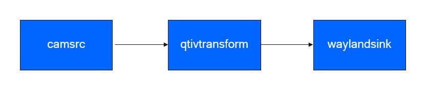
目前只支持180度旋转。
水平翻转
gst-launch-1.0 -e qtiqmmfsrc name=camsrc video_0::type=video video_1::type=preview ! video/x-raw,format=NV12,width=1920,height=1080,framerate=30/1 ! qtivtransform engine=gles flip-horizontal=true ! waylandsink fullscreen=true
垂直翻转
gst-launch-1.0 -e qtiqmmfsrc name=camsrc video_0::type=video video_1::type=preview ! video/x-raw,format=NV12,width=1920,height=1080,framerate=30/1 ! qtivtransform engine=gles flip-vertical=true ! waylandsink fullscreen=true
故障排除
如果摄像头无法显示或捕捉图像,请检查以下内容:
-
参阅 摄像头排线安装检查摄像头模块连接。
-
检查传感器探头。
-
使用以下命令收集日志
journalctl -f > /opt/log.txt -
在日志中搜索 "probe success" 。Probe success 意味着摄像头模块已通电并响应 I2C 控制。如果特定传感器没有 "probe success" 日志,则可能是柔性电缆连接或摄像头模块的问题。
以下日志指示探测到一个 IMX477:
[ 80.645992] CAM_INFO: CAM-SENSOR: cam_sensor_driver_cmd: 939: Probe success,slot:7,slave_addr:0x34,sensor_id:0x477, is always on: 0
-
-
检查摄像头传感器驱动程序命令
-
使用
journalctl -f > /opt/log.txt命令收集日志. -
搜索 "cam_sensor_driver_cmd" 。
-
"CAM_START_DEV Success" 表示摄像头传感器流式传输开始。
-
"CAM_STOP_DEV Success" 表示摄像头传感器流式传输停止。
例如:
start:
[   81.172814] CAM_INFO: CAM-SENSOR: cam_sensor_driver_cmd: 1129: CAM_START_DEV Success, sensor_id:0x477,sensor_slave_addr:0x34
stop:
[ 88.905241] CAM_INFO: CAM-SENSOR: cam_sensor_driver_cmd: 1157: CAM_STOP_DEV Success, sensor_id:0x477,sensor_slave_addr:0x34 -
-
-
检查传感器流式传输.
- 启用 CSID SOF/EOF IRQ 日志,随后执行摄像头出流命令
mount -o rw,remount /usr
mount -t debugfs none /sys/kernel/debug/
echo 0x8 > /sys/module/camera/parameters/debug_mdl
echo 3 >/sys/kernel/debug/camera_ife/ife_csid_debug
echo 1 > /sys/kernel/tracing/tracing_on
echo 1 > /sys/kernel/tracing/events/camera/cam_log_debug/enable
echo 2 > /sys/module/camera/parameters/debug_type
cat /sys/kernel/tracing/trace_pipe > trace.txt-
捕获的日志有助于提供有关 SOF 和 EOF 的详细信息。在日志 "trace.txt" 中搜索 "irq_status_ipp"。
-
BIT12(0x1000)表示 SOF 数据包
-
BIT9(0x200)表示 EOF 数据包。
日志如下所示:
<idle>-0       [000] d.h1. 19287.546764: cam_log_debug:
CAM_DBG: CAM-ISP: cam_ife_csid_irq: 4996: irq_status_ipp = 0x1110 cam-server-25604     [000] dNH.. 19287.561705: cam_log_debug:
CAM_DBG: CAM-ISP: cam_ife_csid_irq: 4996: irq_status_ipp = 0xee8 -