40-pin LS connector
GPIO
RUBIK Pi 3 is compatible with WiringRP (based on the high-performance GPIO programming library WiringPi). It is recommended to use WiringRP for controlling and programming General-Purpose Inputs/Outputs (GPIOs). For more details about WiringRP, visit https://github.com/rubikpi-ai/WiringRP.
Pinout
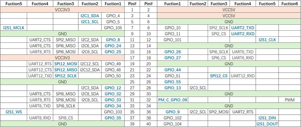
The figure below shows the default functions of the RUBIK Pi 3 40-pin LS connector, most of which are compatible with the default functions of the 40-pin connector of open-source development boards.
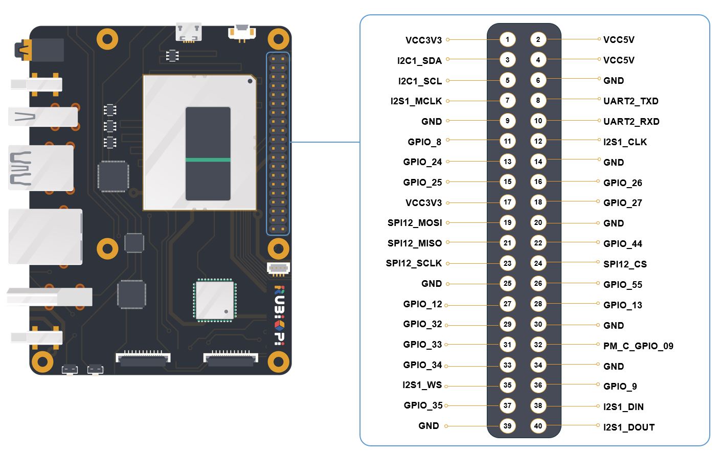
The following table lists all the functions of the 40-pin LS connector, where the default ones are bolded in blue.

Use GPIOs
On RUBIK Pi 3, you can use shell commands or programming languages to control the General-Purpose Input/Output (GPIO).
- Shell command
- WiringRP
- C
- Python
Perform the following steps on your RUBIK Pi 3 to control GPIOs.
The following commands require the root privilege:
- Use the
sudo sucommand to switch to the root user.
-
Using WiringRP commands:
Before using the WiringRP commands, install the WiringRP as follows:
-
Add the RUBIK Pi public personal package archive (PPA) to your RUBIK Pi 3 Ubuntu software sources.
REPO_ENTRY="deb http://apt.thundercomm.com/rubik-pi-3/noble ppa main"if ! grep -q "^[^#]*$REPO_ENTRY" /etc/apt/sources.list; thensudo sed -i '$a deb http://apt.thundercomm.com/rubik-pi-3/noble ppa main' /etc/apt/sources.listfisudo apt update -
Run the following command to install WiringRP.
sudo apt install wiringrpUse the following commands to operate GPIOs after installation:
-
View the GPIO status
gpio readall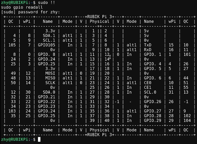
-
Set the GPIO mode
gpio mode 15 in # Set pin 15 to input modegpio pins # Check the modegpio mode 15 out # Set pin 15 to output modegpio pins # Check the mode -
Set the pin level
gpio write 15 1 # Set pin 15 to high levelgpio read 15 # Check the pin levelgpio write 15 0 # Set pin 15 to low levelgpio read 15 # Check the pin level -
Operate nodes under /sys/class/gpio:
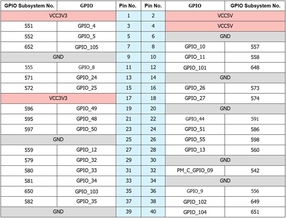
The table below shows the GPIO subsystem numbering.
-
Go to the /sys/class/gpio directory:
cd /sys/class/gpio -
Export the GPIO to be controlled. For example, pin 13 GPIO_24:
echo 571 > export -
Go to the gpio571 directory to set GPIO attributes:
cd gpio571ls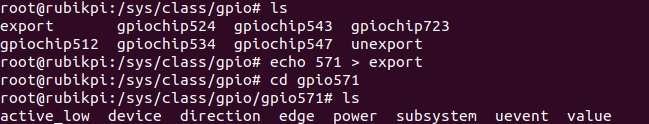
- direction:
- input: in
- output: out
- value:
- Low level: 0
- High level: 1
- edge (interrupt edge):
-
Rising edge trigger: rising
-
Falling edge trigger: falling
-
Both-edge trigger: both
-
Disabling interrupts: none
-
- For example, set pin 13 to output a high level:
echo out > directionecho 1 > value- Cancel the export of pin 13 to user space:
cd ..echo 571 > unexport -
The WiringRP library provides a set of API functions that enable control with minimal logic.
To install the WiringRP library on the RUBIK Pi 3, follow these steps:
- Add the RUBIK Pi public personal package archive (PPA) to your RUBIK Pi 3 Ubuntu software sources.
REPO_ENTRY="deb http://apt.thundercomm.com/rubik-pi-3/noble ppa main"
if ! grep -q "^[^#]*$REPO_ENTRY" /etc/apt/sources.list; then
    sudo sed -i '$a deb http://apt.thundercomm.com/rubik-pi-3/noble ppa main' /etc/apt/sources.list
fi
sudo apt update
- Run the following command to install WiringRP.
sudo apt install wiringrp
The following code snippet is an example that sets pin 13 as output, pin 15 as input, and loops to check the level status of pin 15.
#include <stdio.h>
#include <wiringPi.h>
int main (void)
{
wiringPiSetup () ;
pinMode (13, OUTPUT) ;
pinMode (15, INPUT) ;
for (;;)
{
digitalWrite (13, HIGH) ; // On
printf("%d\n", digitalRead (15)); // On
delay (1000) ; // mS
digitalWrite (13, LOW) ; // Off
printf("%d\n", digitalRead (15)); // On
delay (1900) ;
}
return 0 ;
}
-
Compile on RUBIK Pi 3
gcc gpio.c -o gpio -lwiringPinoteIf the
gcccommand is not available, runapt install gccto install the gcc compiler.
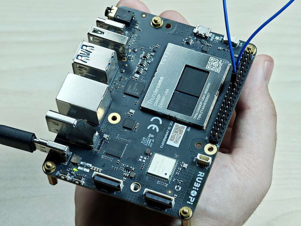
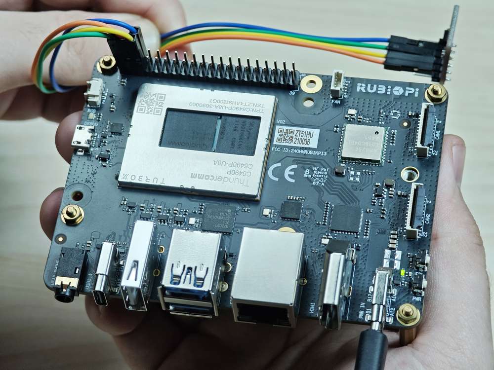
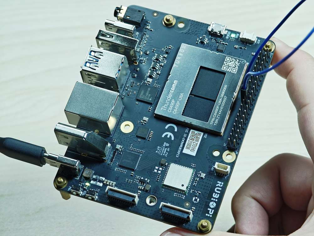
Short pin 13 and pin 15 with a Dupont wire, as shown in the following figure, to test the GPIO level control and read the level.
Pay attention to the pin order. Do not short the power and ground pins, as this may cause damage to the board.

Run the following command:
./gpio
The program execution result is as follows:

The following code snippet is an example that sets pin 13 as output, pin 15 as input, and loops to check the level status of pin 15.
#include <stdio.h>
#include <stdlib.h>
#include <unistd.h>
int out_gpio = 571;
int in_gpio = 572;
int main() {
char export_path[50] = {};
char export_command[100] = {};
snprintf(export_path, sizeof(export_path), "/sys/class/gpio/export");
snprintf(export_command, sizeof(export_command), "echo %d > %s ", out_gpio, export_path);
system(export_command);
snprintf(export_command, sizeof(export_command), "echo %d > %s ", in_gpio, export_path);
system(export_command);
char direction_path[50] = {};
snprintf(direction_path, sizeof(direction_path), "/sys/class/gpio/gpio%d/direction", out_gpio);
FILE *direction_file = fopen(direction_path, "w");
if (direction_file == NULL) {
perror("Failed to open GPIO direction file");
return -1;
}
fprintf(direction_file, "out");
fclose(direction_file);
snprintf(direction_path, sizeof(direction_path), "/sys/class/gpio/gpio%d/direction", in_gpio);
direction_file = fopen(direction_path, "w");
if (direction_file == NULL) {
perror("Failed to open GPIO direction file");
return -1;
}
fprintf(direction_file, "in");
fclose(direction_file);
char value_in_path[50] = {};
char value_out_path[50] = {};
char cat_command[100] = {};
snprintf(value_out_path, sizeof(value_out_path), "/sys/class/gpio/gpio%d/value", out_gpio);
snprintf(value_in_path, sizeof(value_in_path), "/sys/class/gpio/gpio%d/value", in_gpio);
snprintf(cat_command, sizeof(cat_command), "cat %s", value_in_path);
FILE *value_out_file = fopen(value_out_path, "w");
if (value_out_file == NULL) {
perror("Failed to open GPIO value file");
return -1;
}
for (int i = 0; i < 5; i++) {
fprintf(value_out_file, "1");
fflush(value_out_file);
system(cat_command);
sleep(1);
fprintf(value_out_file, "0");
fflush(value_out_file);
system(cat_command);
sleep(1);
}
fclose(value_out_file);
char unexport_path[50] = {};
char unexport_command[100] = {};
snprintf(unexport_path, sizeof(unexport_path), "/sys/class/gpio/unexport");
snprintf(unexport_command, sizeof(unexport_command), "echo %d > %s ", out_gpio, unexport_path);
system(unexport_command);
snprintf(unexport_command, sizeof(unexport_command), "echo %d > %s ", in_gpio, unexport_path);
system(unexport_command);
return 0;
}
Compile on RUBIK Pi 3
gcc gpio.c -o gpio
If the gcc command is not available, run apt install gcc to install the gcc compiler.
Short pin 13 and pin 15 with a Dupont wire, as shown in the following figure, to test the GPIO level control and read the level.
Pay attention to the pin order. Do not short the power and ground pins, as this may cause damage to the board.
Run the following command:
./gpio
The program execution result is as follows:

GPIOs can be controlled by using python-periphery. Run the following command to install python-periphery on RUBIK Pi 3:
apt install python3-pip
apt install python3-periphery
The following code snippet is an example that sets pin 13 as output, pin 15 as input, and loops to check the level status of pin 15.
from periphery import GPIO
import time
out_gpio = GPIO(571, "out")
in_gpio = GPIO(572, "in")
try:
while True:
try:
out_gpio.write(True)
pin_level = in_gpio.read()
print(f"in_gpio level: {pin_level}")
out_gpio.write(False)
pin_level = in_gpio.read()
print(f"in_gpio level: {pin_level}")
time.sleep(1)
except KeyboardInterrupt:
out_gpio.write(False)
break
except IOError:
print("Error")
finally:
out_gpio.close()
in_gpio.close()
Short pin 13 and pin 15 with a Dupont wire, as shown in the following figure, to test the GPIO level control and read the level.
Pay attention to the pin order. Do not short the power and ground pins, as this may cause damage to the board.

Run the following command:
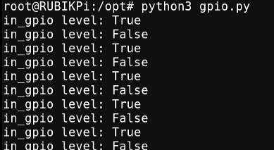
python3 gpio.py
The program execution result is as follows:
I2C
Inter-Integrated circuit (I2C) is a bidirectional 2-wire bus for an efficient inter‑IC control bus developed by Philips in the 1980s. Every device on the bus has its own unique address (registered with the I2C general body headed by Philips). The I2C core supports multicontroller mode, 10‑bit target addressing, and 10‑bit extendable addressing. For more information on I2C, see https://www.i2c-bus.org/fileadmin/ftp/i2c_bus_specification_1995.pdf.
RUBIK Pi 3 is compatible with WiringRP (based on the high-performance GPIO programming library WiringPi). It is recommended to use WiringRP for controlling and programming I2C. For more details about WiringRP, visit https://github.com/rubikpi-ai/WiringRP.
Pinout
The figure below shows the default functions of the RUBIK Pi 3 40-pin LS connector, most of which are compatible with the default functions of the 40-pin connector of open-source development boards.
Pin 3 and pin 5 are set to I2C1 by default.
The following table lists all functions of the 40-pin LS connector, where the default ones are bolded in blue.

Use I2C
On RUBIK Pi 3, you can use shell commands or programming languages to control the I2C bus.
- Shell command
- WiringRP
- C
- Python
Perform the following steps on RUBIK Pi 3 to control the I2C bus. To install the WiringRP library on your RUBIK Pi 3, follow these steps:
- Add the RUBIK Pi public personal package archive (PPA) to your RUBIK Pi 3 Ubuntu software sources.
REPO_ENTRY="deb http://apt.thundercomm.com/rubik-pi-3/noble ppa main"
if ! grep -q "^[^#]*$REPO_ENTRY" /etc/apt/sources.list; then
    sudo sed -i '$a deb http://apt.thundercomm.com/rubik-pi-3/noble ppa main' /etc/apt/sources.list
fi
sudo apt update
- To install the WiringRP library on the RUBIK Pi 3, follow these steps:
sudo apt install wiringrp
-
Use the WiringRP related command:
./gpio -x ads1115:100:10 aread 100 #Read the analog signal value of the ADS1115 device via the I2C bus. -
Use the i2cdetect tool
-
View devices connected to the I2C1 interface:
i2cdetect -a -y -r 1 -
Read all registers of the device whose address is 0x38:
i2cdump -f -y 1 0x38 -
Write 0xaa to register 0x01 of the device whose address is 0x38:
i2cset -f -y 1 0x38 0x01 0xaa -
Read the value at register 0x01 of the device whose address is 0x38:
i2cget -f -y 1 0x38 0x01
-
If commands like i2cdetect are not available, run apt install i2c-tools to install the i2c-tools package.
The WiringRP library provides a set of API functions that enable control with minimal logic.
To install the WiringRP library on your RUBIK Pi 3, follow these steps:
- Add the RUBIK Pi public personal package archive (PPA) to your RUBIK Pi 3 Ubuntu software sources.
REPO_ENTRY="deb http://apt.thundercomm.com/rubik-pi-3/noble ppa main"
if ! grep -q "^[^#]*$REPO_ENTRY" /etc/apt/sources.list; then
    sudo sed -i '$a deb http://apt.thundercomm.com/rubik-pi-3/noble ppa main' /etc/apt/sources.list
fi
sudo apt update
- Run the following command to install WiringRP.
sudo apt install wiringrp
The following code snippet uses the I2C1 bus to communicate with a device whose address is 0x38: write 0xaa to the 0x01 address of the device.
#include <wiringPi.h>
#include <wiringPiI2C.h>
#include <stdio.h>
#include <stdlib.h>
#include <unistd.h>
#define I2C_ADDRESS 0x38
int main(void)
{
int fd;
if (wiringPiSetup() == -1) {
exit(1);
}
fd = wiringPiI2CSetup(1, I2C_ADDRESS);
if (fd == -1) {
exit(1);
}
unsigned char data[2];
if (read(fd, data, 2) != 2) {
exit(1);
}
wiringPiI2CWriteReg8(fd, 0x01, 0xaa) ;
close(fd);
return 0;
}
Compile on RUBIK Pi 3:
gcc i2c.c -o i2c -lwiringPi
If the gcc command is not available, run apt install gcc to install the gcc compiler.
Connect pin 3 and pin 5 to the I2C sensor and test the I2C communication as shown in the following figure.
Pay attention to the pin order. Do not short the power and ground pins, as this may cause damage to the board.

Run the following command:
./i2c
The following code snippet uses the I2C1 bus to communicate with a device whose address is 0x38: write 0xaa to the 0x01 address of the device.
#include <stdio.h>
#include <stdlib.h>
#include <stdint.h>
#include <fcntl.h>
#include <unistd.h>
#include <linux/i2c-dev.h>
#include <sys/ioctl.h>
#define I2C_DEVICE_PATH "/dev/i2c-1"
int main() {
uint8_t data[2] = {0x01,0xaa};
const char *i2c_device = I2C_DEVICE_PATH;
int i2c_file;
if ((i2c_file = open(i2c_device, O_RDWR)) < 0) {
perror("Failed to open I2C device");
return -1;
}
ioctl(i2c_file, I2C_TENBIT, 0);
ioctl(i2c_file, I2C_RETRIES, 5);
printf("i2cdetect addr : ");
for (int x = 0; x < 0x7f; x++)
{
if (ioctl(i2c_file, I2C_SLAVE, x) < 0) {
perror("Failed to set I2C slave address");
close(i2c_file);
return -1;
}
if (write(i2c_file, data, 2) == 2)
{
printf("0x%x,", x);
}
}
close(i2c_file);
printf("\r\n");
return 0;
}
Compile on RUBIK Pi 3:
gcc i2c.c -o i2c
If the gcc command is not available, run apt install gcc to install the gcc compiler.
Connect pin 3 and pin 5 to the I2C sensor to test the I2C bus communication, as shown in the following figure.
Pay attention to the pin order. Do not short the power and ground pins, as this may cause damage to the board.
Run the following command:
./i2c
The program execution result is as follows:

I2C can be controlled by using the Python smbus library. Run the following command on RUBIK Pi 3 to install the library.
apt install python3-smbus
The following code snippet uses the I2C1 bus to communicate with a device whose address is 0x38: write 0xaa to the 0x01 address of the device.
import smbus
def main():
data = [0x01, 0xaa]
try:
i2c_bus = smbus.SMBus(1)
print("i2cdetect addr : ", end="")
for address in range(0x7F):
try:
i2c_bus.write_i2c_block_data(address, 0, data)
print("0x{:02X},".format(address), end="")
except OSError:
pass
print()
except Exception as e:
print(f"An error occurred: {e}")
finally:
if i2c_bus:
i2c_bus.close()
if __name__ == "__main__":
main()
Connect pin 3 and pin 5 to the I2C sensor and test the I2C communication as shown in the following figure.
Pay attention to the pin order. Do not short the power and ground pins, as this may cause damage to the board.

Run the following command:
python3 i2c.py
The execution result is as follows:

SPI
Serial Peripheral Interface (SPI) is a synchronous serial data link that operates in full-duplex mode. SPI is also known as a 4-wire serial bus.
RUBIK Pi 3 is compatible with WiringRP (based on the high-performance GPIO programming library WiringPi). It is recommended to use WiringRP for controlling and programming SPI. For more details about WiringRP, visit https://github.com/rubikpi-ai/WiringRP.
Pinout
The figure below shows the default functions of the RUBIK Pi 3 40-pin LS connector, most of which are compatible with the default functions of the 40-pin connector of open-source development boards.
Pins 19, 21, 23, and 24 are set to SPI by default.
The following table lists all functions of the 40-pin LS connector, where the default ones are bolded in blue.

Use SPI
- WiringRP
- C
- Python
The WiringRP library provides a set of API functions that enable control with minimal logic.
To install WiringRP on your RUBIK Pi 3, follow these steps:
- Add the RUBIK Pi public personal package archive (PPA) to your RUBIK Pi 3 Ubuntu software sources.
REPO_ENTRY="deb http://apt.thundercomm.com/rubik-pi-3/noble ppa main"
if ! grep -q "^[^#]*$REPO_ENTRY" /etc/apt/sources.list; then
    sudo sed -i '$a deb http://apt.thundercomm.com/rubik-pi-3/noble ppa main' /etc/apt/sources.list
fi
sudo apt update
- Run the following command to install WiringRP.
sudo apt install wiringrp
The following code snippet uses the SPI bus to send and receive data.
#include <wiringPi.h>
#include <wiringPiSPI.h>
#include <stdio.h>
#include <stdlib.h>
int main(void)
{
int fd;
unsigned char send_data[64] = "hello world!";
unsigned char read_data[64];
if(wiringPiSetup() == -1)
exit(1);
fd = wiringPiSPISetup(0, 1000000);
if(fd < 0)
exit(2);
printf("\rtx_buffer: \n %s\n ", send_data);
// Send and receive data
if(wiringPiSPIDataRW(0, send_data, sizeof(send_data)) < 0)
exit(3);
printf("\rtx_buffer: \n %s\n ", send_data);
return 0;
}
Compile programs
Compile on RUBIK Pi 3
gcc spi.c -o spi -lwiringPi
If the gcc command is not available, run apt install gcc to install the gcc compiler.
Short pin 19 and pin 21 with a Dupont wire to test the SPI bus communication, as shown in the following figure:
Pay attention to the pin order. Do not short the power and ground pins, as this may cause damage to the board.
Run the following command:
./spi
The execution result is as follows:

The following code snippet uses the SPI bus to send and receive data.
#include <stdio.h>
#include <stdlib.h>
#include <stdint.h>
#include <fcntl.h>
#include <unistd.h>
#include <linux/spi/spidev.h>
#include <sys/ioctl.h>
#define SPI_DEVICE_PATH "/dev/spidev12.0"
int main() {
int spi_file;
uint8_t tx_buffer[50] = "hello world!";
uint8_t rx_buffer[50];
// Open the SPI device
if ((spi_file = open(SPI_DEVICE_PATH, O_RDWR)) < 0) {
perror("Failed to open SPI device");
return -1;
}
// Configure SPI mode and bits per word
uint8_t mode = SPI_MODE_0;
uint8_t bits = 8;
if (ioctl(spi_file, SPI_IOC_WR_MODE, &mode) < 0) {
perror("Failed to set SPI mode");
close(spi_file);
return -1;
}
if (ioctl(spi_file, SPI_IOC_WR_BITS_PER_WORD, &bits) < 0) {
perror("Failed to set SPI bits per word");
close(spi_file);
return -1;
}
// Perform SPI transfer
struct spi_ioc_transfer transfer = {
.tx_buf = (unsigned long)tx_buffer,
.rx_buf = (unsigned long)rx_buffer,
.len = sizeof(tx_buffer),
.delay_usecs = 0,
.speed_hz = 1000000, // SPI speed in Hz
.bits_per_word = 8,
};
if (ioctl(spi_file, SPI_IOC_MESSAGE(1), &transfer) < 0) {
perror("Failed to perform SPI transfer");
close(spi_file);
return -1;
}
/* Print tx_buffer and rx_buffer*/
printf("\rtx_buffer: \n %s\n ", tx_buffer);
printf("\rrx_buffer: \n %s\n ", rx_buffer);
// Close the SPI device
close(spi_file);
return 0;
}
Compile on RUBIK Pi 3
gcc spi.c -o spi
If the gcc command is not available, run apt install gcc to install the gcc compiler.
Short pin 19 and pin 21 with a Dupont wire to test the SPI bus communication, as shown in the following figure.
Pay attention to the pin order. Do not short the power and ground pins, as this may cause damage to the board.

Run the following command:
./spi
The program execution result is as follows:
SPI communication can be implemented by using the spidev library for Python. Run the following command to install spidev on RUBIK Pi 3.
apt install python3-spidev
The following code snippet uses the SPI bus to send and receive data.
import spidev
def main():
tx_buffer = [ord(char) for char in "hello world!"]
rx_buffer = [0] * len(tx_buffer)
try:
spi = spidev.SpiDev()
spi.open(12, 0)
spi.max_speed_hz = 1000000
rx_buffer = spi.xfer2(tx_buffer[:])
print("tx_buffer:\n\r", ''.join(map(chr, tx_buffer)))
print("rx_buffer:\n\r", ''.join(map(chr, rx_buffer)))
except Exception as e:
print(f"An error occurred: {e}")
finally:
if spi:
spi.close()
if __name__ == "__main__":
main()
Short pin 19 and pin 21 with a Dupont wire to test the SPI bus communication, as shown in the following figure.
Pay attention to the pin order. Do not short the power and ground pins, as this may cause damage to the board.

Run the following command on your RUBIK Pi 3:
python3 spi.py
The program execution result is as follows:

UART
RUBIK Pi 3 is compatible with WiringRP (based on the high-performance GPIO programming library WiringPi). It is recommended to use WiringRP for controlling and programming UART. For more details about WiringRP, visit https://github.com/rubikpi-ai/WiringRP.
Pinout
The figure below shows the default functions of the RUBIK Pi 3 40-pin LS connector, most of which are compatible with the default functions of the 40-pin connector of open-source development boards.
Pins 8 and 10 have been set to UART by default. The device node is /dev/ttyHS2.
The following table lists all functions of the 40-pin LS connector, where the default ones are bolded in blue.
Use UART
- Shell command
- WiringRP
- C
- Python
Run the following commands on RUBIK Pi 3 to control UART communication.
Use the stty tool to configure UART. Run the following commands to set both the input rate and output rate of UART to 115200 and disable the echo.
stty -F /dev/ttyHS2 ispeed 115200 ospeed 115200
stty -F /dev/ttyHS2 -echo
Enable two terminals on RUBIK Pi 3, short pin 8 and pin 10 with a Dupont wire, and run the following commands. The content sent by the transmitter will be displayed on the receiver.
Pay attention to the pin order. Do not short the power and ground pins, as this may cause damage to the board.
echo "hello world!" > /dev/ttyHS2 # Transmitter
cat /dev/ttyHS2 # Receiver
The WiringRP library provides a set of API functions that enable control with minimal logic.
To install WiringRP on your RUBIK Pi 3, follow these steps:
- Add the RUBIK Pi public personal package archive (PPA) to your RUBIK Pi 3 Ubuntu software sources.
REPO_ENTRY="deb http://apt.thundercomm.com/rubik-pi-3/noble ppa main"
if ! grep -q "^[^#]*$REPO_ENTRY" /etc/apt/sources.list; then
    sudo sed -i '$a deb http://apt.thundercomm.com/rubik-pi-3/noble ppa main' /etc/apt/sources.list
fi
sudo apt update
- Run the following command to install WiringRP.
sudo apt install wiringrp
The following code snippet uses UART to send and receive data:
#include <stdio.h>
#include <string.h>
#include <errno.h>

#include <wiringPi.h>
#include <wiringSerial.h>

int main ()
{
  int fd ;
  int count ;
  unsigned int nextTime ;

  if ((fd = serialOpen ("/dev/ttyHS2", 115200)) < 0)
  {
    fprintf (stderr, "Unable to open serial device: %s\n", strerror (errno)) ;
    return 1 ;
  }

  if (wiringPiSetup () == -1)
  {
    fprintf (stdout, "Unable to start wiringPi: %s\n", strerror (errno)) ;
    return 1 ;
  }


  char tx_buffer[] = "hello world!\n";
  for (count = 0 ; count < sizeof(tx_buffer) ; count++)
  {
    serialPutchar (fd, tx_buffer[count]) ;
    delay (3) ;
    printf ("%c", serialGetchar (fd)) ;
  }
  printf ("\n") ;

  return 0 ;
}
Compile on RUBIK Pi 3
gcc uart.c -o uart -lwiringPi
If the gcc command is not available, run apt install gcc to install the gcc compiler.
Short pin 8 and pin 10 with a Dupont wire and test the communication, as shown in the following figure:
Pay attention to the pin order. Do not short the power and ground pins, as this may cause damage to the board.

Run the following command:
./uart
The execution result is as follows:

-
The following code snippet uses UART to send and receive data.
#include <stdio.h>#include <stdlib.h>#include <string.h>#include <fcntl.h>#include <termios.h>#include <unistd.h>int main() {int serial_port_num = 2;char serial_port[15];sprintf(serial_port,"/dev/ttyHS%d",serial_port_num);int serial_fd;serial_fd = open(serial_port, O_RDWR | O_NOCTTY);if (serial_fd == -1) {perror("Failed to open serial port");return 1;}struct termios tty;memset(&tty, 0, sizeof(tty));if (tcgetattr(serial_fd, &tty) != 0) {perror("Error from tcgetattr");return 1;}cfsetospeed(&tty, B9600);cfsetispeed(&tty, B9600);tty.c_cflag &= ~PARENB;tty.c_cflag &= ~CSTOPB;tty.c_cflag &= ~CSIZE;tty.c_cflag |= CS8;if (tcsetattr(serial_fd, TCSANOW, &tty) != 0) {perror("Error from tcsetattr");return 1;}char tx_buffer[] = "hello world!\n";ssize_t bytes_written = write(serial_fd, tx_buffer, sizeof(tx_buffer));if (bytes_written < 0) {perror("Error writing to serial port");close(serial_fd);return 1;}printf("\rtx_buffer: \n %s ", tx_buffer);char rx_buffer[256];int bytes_read = read(serial_fd, rx_buffer, sizeof(rx_buffer));if (bytes_read > 0) {rx_buffer[bytes_read] = '\0';printf("\rrx_buffer: \n %s ", rx_buffer);} else {printf("No data received.\n");}close(serial_fd);return 0;}Compile on RUBIK Pi 3
gcc uart.c -o uartnoteIf the
gcccommand is not available, runapt install gccto install the gcc compiler.Short pin 8 and pin 10 with a Dupont wire to test UART communication, as shown in the following figure:
warningPay attention to the pin order. Do not short the power and ground pins, as this may cause damage to the board.

Run the following command:
./uartThe execution result is as follows:

UART communication can be implemented by using the serial library for Python. Run the following command to install the serial library on RUBIK Pi 3.
apt install python3-serial
The following code snippet uses UART to send and receive data.
import serial
import time

with serial.Serial(
    "/dev/ttyHS2",
    baudrate=115200,
    bytesize=serial.EIGHTBITS,
    stopbits=serial.STOPBITS_ONE,
    parity=serial.PARITY_NONE,
    timeout=1,

) as uart3:
    uart3.write(b"Hello World!\n")
    buf = uart3.read(128)
    print("Raw data:\n", buf)
    data_strings = buf.decode("utf-8")
    print("Read {:d} bytes, printed as string:\n {:s}".format(len(buf), data_strings))
Transfer uart.py to RUBIK Pi 3. For example, use the ADB method. The command is as follows:
adb push uart.py /opt
Short pin 8 and pin 10 with a Dupont wire to test UART communication, as shown in the following figure:
Pay attention to the pin order. Do not short the power and ground pins, as this may cause damage to the board.

Run the following command:
python3 uart.py
The execution result is as follows:
